1993 Bronco Wont Shift please help

Disclaimer: Links on this page pointing to Amazon, eBay and other sites may include affiliate code. If you click them and make a purchase, we may earn a small commission.

Bmarlowe30

New member
Joined
Aug 11, 2016
Messages
36
Reaction score
0
Location
Midland, Tx.
ok I have a 1993 Ford Bronco 4x4 with E4OD Transmission. When I shift it into drive it will not go into the lower gears. It stays in high unless you manually shift it into lower gears. Also the Speedometer is not working. I believe these issues are related.

When I bought this bronco it already had this problem and got no info from the previous owner. I have been working on it for over a year to no avail.

Here is what I have done so far

1.Replaced the speed sensor 3 times just to make sure I got a good part

2.Checked continuity through every wire in the transmission wiring harness

3.Replaced Transmission and Torque Converter

4.Transmission oil and filter

5.Replaced the Plug itself going to the speed sensor

6.Spun the wheels and checked the speed sensor with a volt meter and it checked out great

7.Replaced the neutral safety switch twice

8.Replaced Throttle Position Sensor

9.Replaced Engine wiring harness complete with fuse box

10.Replaced the Computer or ECU twice

11.New Instrument Cluster

12.Checked the tone ring in the rear differential

13.Checked continuity of the wires from the Speed Sensor on the rear Differential all the way to the plug at the firewall

14.Replaced all fuses

15.Replaced all light front and back and all work

16.Checked and repaired all vacuum hoses

17.Taken everything apart checking for pinched wires and none were found

I have a friend that has owned a Mechanic shop for over 30 years and has worked on my cars and our company vehicles and he cannot figure it out.

Also have a friend that is the best Transmission specialist here and he cant figure it out.

I love this bronco I just want it to be fixed..

Please I beg you someone help me out

Thanks

  Brian


miesk5

96 Bronco 5.0
Staff member
Moderator
Joined
Oct 18, 2005
Messages
9,078
Reaction score
1,037
Location
Floating in the Pacific
Yo Brian,

Welcome!

I assume the cluster included a different PSOM (Speedo)?

Did you replace or bypass the 4WABS Control Module? "...A new light truck 4-Wheel ABS was introduced as standard equipment on the 93 Bronco, and it was revised in 94 on Broncos, requiring a different control module revision for 94 to 96 Broncos, compared to the original 93 Bronco module. The anti-lock brake electronic control module is located in the engine compartment behind the driver's side head lamp on a bracket mounted on the surface of the plastic fender apron. The anti-lock brake electronic control module monitors system operation during normal driving as well as during anti-lock braking.

***In addition, the anti-lock brake electronic control module provides a speed signal to the programmable speedometer/odometer module (PSOM) and to the E4OD via the PCM and for speed control ***

My 96's similar symptoms were almost the same until the 4WABS Module's microprocessors finally burnt-out. 2 yard Modules were bad so I jumpered the Module out as Turbo Ghost describes below.

My 96's same symptoms were erratic until the 4WABS Module's microprocessors finally burnt-out. I had one go bad and 2 yard Modules were also bad; so I jumpered the Module out as Steve & Turbo Ghost describes below.

To bypass the 4WABS module @ it's harness's connector & feed the ABS signal directly to the PSOM.

Disconnect module (under coolant recovery /ws washer tank) & in connector, jumper LG/Bk to LG/Y, and R/Pk to O/LB.

Module uses a 10mm bolt to hold the connector in place. Loosen the bolt (it doesn't come out, just loosens) and pull the connector from the module. Then jump the pins as shown in the pic and place the connector in a safe position so the jumpers won't get knocked loose while driving. Make sure the connections are good and clean and the jumpers are firmly in place. Contact cleaner will help. Then, drive the vehicle a short distance and you should immediately regain your speedometer/etc. If you do not, then your problem is NOT the module.

http://img.photobucket.com/albums/v252/turboghost/ABSConnectorw-jumpers.jpg

---------

Here is more info, most of which you have done;

This problem could be caused by a # of things;

bad vehicle speed sensor (VSS) (also called ABS,, DSS sensor) on the 8.8 (rear differential)/ or corroded Connector/ wires inside connector; many NON-FORD MOTORCRAFT sensors ARE REPORTED DEFECTIVE BY OWNERS, such as;

"... The VSS was probably working fine the entire time (except the DOA Vatozone ones)..."

by ****-sidewards

"...Anyway, the autozone VSS looks almost identical to the ford VSS. They are both now made of plastic. You have to look very closely to see minor differences. However, the magnet inside does not budge in the ford part, no rattling noise at all. The Autozone part rattles when shaken, ie. the magnet has room to move inside the plastic housing.[/b]It's was a big lesson for me. Wrong readings from the VSS can cause so much E4OD problems...erratic shifting, late shifting, hard shifting, feeling like it was in neutral, as well as engine cutting off at stop lights---Even if it registers correct readings on your speedometer..."

Source: by bkne40d

"i installed a motorcraft speed sensor today (DY1123). i drove it all day today with numerous stops. i tried to make it fail by playing with the overdrive switch. it seems as though it was my failure by not buying a motorcraft sensor to begin with. i think the truck is fixed. shame on me for trusting BWD, i suppose. but also, shame on all parts stores for failing to list a speed sensor from motorcraft for my car! to my defense, there was no motorcraft number listed for my car at any of the parts stores. What i find most interesting is a potential indication of WHY the motorcraft is better, other than the labeling. below are pics of all three sensors next to each other. the difference seems to be in the size of the magnet/sensor in the motorcraft compared to the BWD part.

also, good on oreilly's for happily giving me a refund on the two BWD parts."

by dash_cam

or cruddy/damaged tone ring in the 8.8.

bad 4WABS Module - It is located below ws wiper fluid/coolant recovery tank. So, the connector can be corroded by leaking fluid

bad PSOM (Speedo)

bad wiring/shorts /connectors from VSS at firewall, at 4WABS Module and /or at PSOM and then onto the PCM

The locations of the connectors along the path from VSS to 4WABS and up to Instr Cluster & PSOM are;

C404 VSS On rear axle sensor (A7) Terminals: 02

C205 LH rear of engine compartment, in safety wall (Fire Wall) Terminals: 24 In-Line

C202F & M LH rear of engine compartment, in safety wall (A8) Terminal: 7 In-Line

C119 LH front corner of engine compartment on 4WABS control module (E10),Terminals: 40

O/LB to:

C202F & M LH rear of engine compartment, in safety wall (A8) Terminal: 7 In-Line

C252 Programmable Speedometer/Odometer Module (PSOM), Behind top LH side of I/P, on PSOM (A7) Terminal: 12 Color: B at Pins 4

LG/Y to Splice S107 Engine control sensor harness, from C119 near T/O to G101 (G101 RH side of Radiator support); to PSOM Pin 5

C202 F and M

and spliced to Ground G100 (BK)

G100 & G104 (tied together in diagram) G100 @ LH front of engine compartment, on upper radiator support

G100 Serves Component:

Fuel Pump Module

Inertia Fuel Shutoff

Misfire Sensor aka crankshaft position sensor

Misfire Sensor Shield

Output Shaft Speed (OSS) Sensor

Powertrain Control Module (PCM), 5.0L

G200 Behind bottom of RH cowl panel

Serves Component:

Air Bag Diagnostic Monitor

Electronic Shift Control Module

Instrument Cluster

Programmable Speedometer/Odometer Module (PSOM)

Remote/Keyless Entry Module

Speed Control Servo/Amplifier Assembly

From PSOM Pin 7 (GY/BK) to Splice S246 Main harness, near T/O to speed control amplifier to

C185 PK/O @ PCM 5.0L Powertrain Control Module (PCM) LH side of safety wall, on powertrain control module (PCM) (C10) Terminal: 104 Color: GY

C185, 5.8L Powertrain Control Module (PCM) LH side of safety wall, on powertrain control module (PCM) (C10) Terminal: 104 Color: GY

C185 @PCM to C202 F and M

Splice 216 to Ground G200, Instrument Cluster ground is inside passenger side kick panel

and on to C185 @ PCM PIN 58 (GY/BK) and from Pin 46 to MLPS (TR) Pin 2

Try a Self Test for Diagnostic Trouble Codes (DTC)s by my pal, BroncoJoe19 @

http://broncozone.com/topic/14269-code-reader/?pid=74587&mode=threaded

The engine temperature must be greater than 50° F for the Key On Engine Off (KOEO) Self-Test and greater than 180° F for the Key On Engine Running (KOER) Self-Test.

heat the engine up and shift thru all gears incl Reverse. Then turn off all accessories/lights, etc.

Make sure A/C is off and transmission is in Park (automatic) or in Neutral for a Manual & release clutch.

Do Key On Engine Off (KOEO) portion first.

And Post them here according to:

KOEO

&

KOER

Check Fuses 8 & 18 in Cab fuse block (lower left of dash by driver's left knee)

If no 12 v on Supply Side of each; look in Power Distribution Box (Located under the hood on the drivers side fenderwell, on driver's side of the air cleaner housing)

and check **** FUSES J & S

or cruddy/damaged tone ring in the 8.8.

bad 4WABS Module - It is located below ws wiper fluid/coolant recovery tank. So, the connector can be corroded by leaking fluid

bad PSOM (Speedo)

bad wiring/shorts /connectors from VSS at firewall, at 4WABS Module and /or at PSOM and then onto the PCM

The locations of the connectors along the path from VSS to 4WABS and up to Instr Cluster & PSOM are;

C404 VSS On rear axle sensor (A7) Terminals: 02

C205 LH rear of engine compartment, in safety wall (Fire Wall) Terminals: 24 In-Line

C202F & M LH rear of engine compartment, in safety wall (A8) Terminal: 7 In-Line

C119 LH front corner of engine compartment on 4WABS control module (E10),Terminals: 40

O/LB to:

C202F & M LH rear of engine compartment, in safety wall (A8) Terminal: 7 In-Line

C252 Programmable Speedometer/Odometer Module (PSOM), Behind top LH side of I/P, on PSOM (A7) Terminal: 12 Color: B at Pins 4

LG/Y to Splice S107 Engine control sensor harness, from C119 near T/O to G101 (G101 RH side of Radiator support); to PSOM Pin 5

C202 F and M

and spliced to Ground G100 (BK)

G100 & G104 (tied together in diagram) G100 @ LH front of engine compartment, on upper radiator support

G100 Serves Component:

Fuel Pump Module

Inertia Fuel Shutoff

Misfire Sensor aka crankshaft position sensor

Misfire Sensor Shield

Output Shaft Speed (OSS) Sensor

Powertrain Control Module (PCM), 5.0L

G200 Behind bottom of RH cowl panel

Serves Component:

Air Bag Diagnostic Monitor

Electronic Shift Control Module

Instrument Cluster

Programmable Speedometer/Odometer Module (PSOM)

Remote/Keyless Entry Module

Speed Control Servo/Amplifier Assembly

From PSOM Pin 7 (GY/BK) to Splice S246 Main harness, near T/O to speed control amplifier to

C185 PK/O @ PCM 5.0L Powertrain Control Module (PCM) LH side of safety wall, on powertrain control module (PCM) (C10) Terminal: 104 Color: GY

C185, 5.8L Powertrain Control Module (PCM) LH side of safety wall, on powertrain control module (PCM) (C10) Terminal: 104 Color: GY

C185 @ PCM to C202 F and M

Splice 216 to Ground G200, Instrument Cluster ground is inside passenger side kick panel

and on to C185 @ PCM PIN 58 (GY/BK) and from Pin 46 to MLPS (TR) Pin 2

Verify PCM & MLPS wiring & Pin numbers using following WIRING DIAGRAM by Ford

psom.jpg

....

I messed up this reply due to my lousy tablet and the pop up ads here.

 
OP
OP
Bmarlowe30

Bmarlowe30

New member
Joined
Aug 11, 2016
Messages
36
Reaction score
0
Location
Midland, Tx.
Supreme

  Thanks for the reply. I have read your posts for months and tried everything before posting about it.. if anyone knows I think it wopuld be you.

Now the picture you linked looks to be the computer plug? if so how do you jumper it and still plug it in so it will run.

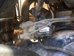
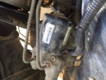
my abs plug looks nothing like that I have attached pictures of mine.

you have no idea how much I appreciate your input

  Brian

IMG_4328 (1).JPG

IMG_4329 (1).JPG


miesk5

96 Bronco 5.0
Staff member
Moderator
Joined
Oct 18, 2005
Messages
9,078
Reaction score
1,037
Location
Floating in the Pacific
Yo,

The jumpered connector is from the ABS module underneath the coolant recovery tank/ws washer tank.

Just jumper the pins shown.

jumper 14 to 21,

39 to 22

You will see The amber ABS light, but hopefully your psomwillmwork and e4od shiftt

 
OP
OP
Bmarlowe30

Bmarlowe30

New member
Joined
Aug 11, 2016
Messages
36
Reaction score
0
Location
Midland, Tx.
that is a picture of the abs module under the tank. it does not have a plug like the on in your picture that I can see.

could it be that module is bad causing all of this?

also what color wires control the speedometer on the inside of the cab?

 
OP
OP
Bmarlowe30

Bmarlowe30

New member
Joined
Aug 11, 2016
Messages
36
Reaction score
0
Location
Midland, Tx.
Everything I looked up does not show my93' has an abs module

only shows to have one on the 5.8 but not with the 5.0

 
Last edited by a moderator:

miesk5

96 Bronco 5.0
Staff member
Moderator
Joined
Oct 18, 2005
Messages
9,078
Reaction score
1,037
Location
Floating in the Pacific
Yo,

Sorry for delays. I am often on in mornings around 0900 hours EDST to early evening hours. It depends on physical therapy home visits. At night, I may appear to be logged in, but that is because I often try to log out, but error messages pop up, so I shut my Tablet down.

Now I can see both of your pics. The pop-up ads here blocked out the 2nd pic yesterday, both pics are of the 4WABS Hydraulic Control Unit (HCU) aka pump, on driver's side.

Here is the 4WABS Control Module PN Label F37A-2C018-BB & 40-pin connector pic in a 93 Bronco. "...NOT for 94-96 Bronco; 94-96 Broncos were built with a different PN module.

4wabsmod.jpg

by Steve

...

Compare this pic to your two pics;

4WABS Hydraulic Control Unit (HCU) pic on right side & Control Module with 40-pin connector on left side in 93-96

4wabshcu.jpg by Steve

4WABS Hydraulic Control Unit (HCU) Description, Location Removal & Installation; "...located outside of the engine compartment on a bracket which attaches to the left frame rail. It consists of the following: Brake pressure control valve block assembly, Pump motor, Hydraulic control unit reservoir w/ a fluid level indicator assembly. Disconnect the battery ground cable. 2.Unplug the 8-pin connector from the unit, and the 4-pin connector from the pump motor. 3.Disconnect the 5 inlet and outlet tubes from the unit. Immediately plug the ports. 4.Remove the 3 unit attaching nuts and lift out the unit. 5.Installation is the reverse of removal. Tighten the mounting nuts to 12-18 ft. lbs. (16-24 Nm) and the tube fittings to 10-18 ft. lbs. (13-24 Nm. After reconnecting the battery, it may take 10 miles or more of driving for the Powertrain Control Module to relearn its driveability codes. 6.Bleed the brakes..." by Ford

...

Do you think a previous owner or shop removed the Control Module?

Look for its 40 pin connector below the washer fluid tank.

Will post this now, then look at your two pics again to view in larger size.

EDIT, your 2 pics are of the 4WABS Hydraulic Control Unit (HCU), aka pump.

Is amber ABS light on with engine running ON?

 
Last edited by a moderator:
OP
OP
Bmarlowe30

Bmarlowe30

New member
Joined
Aug 11, 2016
Messages
36
Reaction score
0
Location
Midland, Tx.
no abs light on. no check engine light.

I have a 12 pin plug with nothing plugged into it.

have not found the control module so may have been removed

 
OP
OP
Bmarlowe30

Bmarlowe30

New member
Joined
Aug 11, 2016
Messages
36
Reaction score
0
Location
Midland, Tx.
just looked under and I have no plug or module like that

also I checked the engine wiring harness I took off and neither it nor the new one have that plug on it

also I have the abs plus going int my front wheel hubs and the plug coming out but they have nothing to plug into

abs plug.jpg

 
Last edited by a moderator:

miesk5

96 Bronco 5.0
Staff member
Moderator
Joined
Oct 18, 2005
Messages
9,078
Reaction score
1,037
Location
Floating in the Pacific
Yo Brian,

Well, previous owner or shop hacked the life out of it. So since you do see the HCU it confirms it did have the 4wabs and a control module, plus front wheel sensors, agree?

Next step is to obtain the needed harness and control module, install and to jump out the module pins.

Will post because I see that you are logged in.

Will find a harness diagram Depiction for you.


miesk5

96 Bronco 5.0
Staff member
Moderator
Joined
Oct 18, 2005
Messages
9,078
Reaction score
1,037
Location
Floating in the Pacific
Yo,

This from 96 Bronco-F-Series Workshop Manual (PARTIAL) by FORD via

http://www.diesel-dave.com/vehic/manual/stj/stjleft.htm

Same as most earlier years especially 92-96, except for: OBD II in 96; 4WABS (93-96); RABS (87-92); Air Bag (94-96); 3 ***** Automatic Locking Hubs (Built from May 95 through 96); Spark Plug Wire Routing & Firing Order (The firing order for 1987-1993 5.0Ls is 1-5-4-2-6-3-7-8. The firing order for 1994- 96 5.0Ls & all 5.8Ls is 1-3-7-2-6-5-4-8.); R134a in 94-96;

2-piece Spindle Rolling Diaphragm Seal (RDS) used on 5/95 to 96 Broncos & F Series 1/2-ton 4WD;

and a few other items that I still need to research such as Mass Air Flow in 95 5.8 California models and in all 96s, other years used Manifold Absolute Pressure Sensor (MAP).

Wiring Harnesses

http://www.diesel-dave.com/vehic/manual/stj/stji1015.htm

See:

Fender Apron, Left, Gasoline Engines

Item Part Number Description

1 33777 Nut

2 16E555 Insulator (Bronco Only)

3 — Locator, Position in Hole Provided (Part of 12A581)

4 — To LH Parking Lights

5 — To LH Air Bag Sensor

6 — To LH Headlamp

7 — To LH Turn and Park

8 12A581 Wiring Assembly

9 — To Canadian Daytime Running Lamp

10 N806972-S36MG ***** to Ground Wire Assembly

11 — To Windshield Washer Pump

***12 2C279 Anti-Lock Brake System Control Module Bracket and Assembly (40 Way) (Bronco Only)

***13 — To Anti-Lock Brake System Control Module

***14 — To Hydraulic Unit (8-Way) (Bronco Only)

***15 — To Pump Motor (4-Way) (Bronco Only)

16 N806327-S190 *****

17 14B005 Sensor and Bracket Assembly

18 8496 Radiator Support

19 — To Intake Air Temperature Sensor

20 9A603 Air Cleaner

21 — To Mass Airflow Sensor

A — Tighten to 9-13 Nm (80-115 Lb-In)

B — Tighten to 5-7 Nm (44-62 Lb-In)

C — Tighten to 10-14 Nm (7-10 Lb-Ft)

 
OP
OP
Bmarlowe30

Bmarlowe30

New member
Joined
Aug 11, 2016
Messages
36
Reaction score
0
Location
Midland, Tx.
I have two wiring harnesses and neither have it.  any idea where I can get a new one that is right?

I think you need to come over and fix this lol I am so dang frustrated

 
Last edited by a moderator:

miesk5

96 Bronco 5.0
Staff member
Moderator
Joined
Oct 18, 2005
Messages
9,078
Reaction score
1,037
Location
Floating in the Pacific
Yo Brian,

I doubt that there any new harnesses around. Give local Ford dealership parts dept.s a call. Would be $$$.

Probably use a yard queen's harness and module. But ensure they guarantee it withn $ back.

For a YARD SEARCH on-line, I use;

http://www.hollanderparts.com/

A yard that uses Hollander Interchange can search other yards and have it shipped to local yard.

Can select certain parts

Has Vehicle Pics! They show about 3 - 5 pics for some vehicles

I selected: 1993 Ford Bronco Electrical Engine Wire Harness Alternate Engine Wire Harness, does not show the module harness.

1993 Ford Bronco Brakes Anti Lock Brake Parts 01228 AssemblY

But has this note, "*All parts shown will fit the searched vehicle, even if they are different years, makes, and/or models." That would not be good for selecting the module.

Has engine bay pics. Looked at only two, but ws washer / coolant recovery tank is in the way, would have to be a pic from overhead to see a piece of the harness or the module.

...

or

http://www.copartfinder.com/finder/searchMake.do

Has Vehicle Pics! They show about 4 - 5 pics per vehicle incl. interior/dash, back seat, front & rear and engine bay.

Can NOT Select certain parts

Typical pic is http://images.copart.com/website/data/pix/20151113/37351935_07X.JPG

...

http://www.car-parts.com/

Can select certain parts

Has Some Vehicle Pics! They show about 4 - 8 pics per vehicle incl. interior/dash, back seat, front & rear and engine bay.

I searched for:

1993 Engine Harness Wiring Ford Bronco Full Size

Each Bronco shown has one engine bay pic, such as this;

https://wsimgproky.car-part.com/2970/2016/160140/2970_31074_07_web.jpg

As you can see ws washer / coolant recovery tank is in the way, would have to be a pic from overhead to see a piece of the harness or the module.

...

http://www.picknpull.com

This is a Company name w/yard locations in various states

Can NOT Select certain parts

http://row52.com/Search

Can NOT Select certain parts

Has Vehicle Pics AND Want a Part? It's Easy...

1. You create a Parts Wanted Listing.

2. Parts Pullers respond with offers.

3. You pick the best one.

A Parts Puller gets the parts you need.

****

for obsolete parts by Ford long version pn:

http://www.partsvoice.com/

http://www.rearcounter.com

http://www.greensalescompany.com

....

Hey, I would help,there, but I am not mobile now. Learning to walk again, but look me up in 2017.


miesk5

96 Bronco 5.0
Staff member
Moderator
Joined
Oct 18, 2005
Messages
9,078
Reaction score
1,037
Location
Floating in the Pacific
Yo,

Thanks for the prayers!

You wrote, "I have two wiring harnesses and neither have it."

Did these come out of a F or E series? If so, they did not have 4wabs until around 97.

Was thinking last night that other harnesses &/or connector and maybe components were hacked or removed. Can you make a list of the sensor's that you are sure are in place and are hooked up, aside from TPS & VSS?

Engine Coolant Temperature (ECT) Sensor

http://www.supermotors.net/getfile/782138/fullsize/what-is-this-2.jpg

...

http://www.fullsizebronco.com/forum/attachment.php?attachmentid=56082&stc=1&d=1420553019

ECT Sensor Location in a 96, same for your 93;

1 ECT Sensor Location (Part of 9424)

2 9F593 Fuel Injector

3 9C968 Fuel Pressure Regulator

4 9D280 Fuel Injection Supply Manifold

5 9D930 Fuel Charging Wiring

6 — Fuel Return Tube (Part of 9F792 Assembly)

7 — IAT Sensor Location (5.8L, 49 States Only)

(Part of 9424)

8 — Water Temperature Sender Location (Part of 9424) this is for temp gauge.

9 — Pressure Relief Valve

(Part of 9F792)

...

Idle Air Control (IAC)

5.8l-dist.jpg

...

Intake Air Temp (IAT); (Air Charge Temperature [ACT] prior to 1992), is in the air cleaner tube on SFI engines.

IAT will have a connector with 2 wires. looks like it plugs right into the intake

iac-(3).jpg

...

Manifold Absolute Pressure (MAP); used only in Speed Density Systems https://www.supermotors.net/getfile/859755/fullsize/map-bap-location.jpg

...

Canister Purge Solenoid (CANP)

p6130044a.jpg

Passenger side, near throttle body

https://www.supermotors.net/getfile/859755/fullsize/map-bap-location.jpg

...

EVP Sensor

Atop EGR valve

evp-egr.jpg

...

Manual Lever Position/Transmission Range (MLP/TR) Sensor

Driver side of E4OD

img_1711.jpg

EGR Vacuum Regulator (EVR), TAB, TAD location pic

http://www.supermotors.net/getfile/848247/fullsize/tab-tad-evr-coil2a.jpg

...

Thermactor Air Bypass Solenoid (TAB, AIRB, AM1) w& Air Bypass Valve (AIR BPV) & Thermactor Air Diverter Solenoid (TAD, AIRD, AM2)

TAD (Diverter) Valve located at the rear of the Intake Manifold on Crossover (aka "Y") tubing at

tad.jpg

You have to climb up onto the engine to feel the Diverter Valve or remove the Intake Manifold. I'd rather climb up using plans, ala a scaffolding type set-up; maybe remove hood depending on circumstances such as me now, w/ backache..." by SeattleFSB

thermactor-air-diverter-valve.jpg

...

VRESER is the Vacuum Reservoir Can

 
Last edited by a moderator:
OP
OP
Bmarlowe30

Bmarlowe30

New member
Joined
Aug 11, 2016
Messages
36
Reaction score
0
Location
Midland, Tx.
ok

1.IAC does not have plug or spot for it

everything else you listed I have and is plugged in.

also have replaced the 4WABS control Module and the MLP or Neutral Safety Switch

one other thing. my overdrive light does not work. I took it apart and repaired the wires and put it back together but still does not work. not sure if that matters just throwing everything out there.

I'm at the point of giving up honestly

 
Last edited by a moderator:

miesk5

96 Bronco 5.0
Staff member
Moderator
Joined
Oct 18, 2005
Messages
9,078
Reaction score
1,037
Location
Floating in the Pacific
Yo,

Hang in there. You found the 4WABS control Module? Did you find the harness connector that needs to be jumped?

..

IAC Location pics in a 93 by Bobby

slide1.jpg

slide3.jpg

...

Alarm... well, that needs to yanked and wiring needs to checked. Can you make out name, part number?

This is stock module,

antitheft-module-003.jpg pic by Mikey350


Members online

No members online now.

Forum statistics

Threads
22,647
Messages
136,846
Members
25,343
Latest member
felixb52
Top