Yo WABRONC,
Welcome!
Here are tests by Ford;
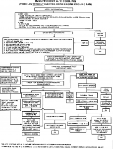
A/C Clutch Cycling Diagnosis
IF THE IMAGE IS TOO SMALL, click it.
ISSUE: Poor air conditioning cooling caused by low or no refrigerant charge often results in unnecessary replacement of the clutch cycling pressure switch. The switch is designed to work on system pressure. It closes at about 46 psi and opens at about 24.5 psi. It has a normal cycle (on and off) rate of 2 to 5 cycles per minute.
ACTION: If an inoperative or fast cycling pressure switch is found, use the following diagnostic charts before replacing the pressure switch.
DIAGNOSTIC PROCEDURE:
1. Connect a manifold gauge set to the service ports and check the system pressures. They should be above the closing pressure of the switch (46 psi).
2. If the A/C system pressures are above 46 psi and the clutch will not engage, proceed as follows:
> Check the pressure switch harness connector and harness wires for a continuous open condition.
> Check for an intermittent open or a poor connection between the connector and the pressure switch terminals.
a. If the harness connector and wire are OK, by-pass the pressure switch by jumping the two terminals of the connector. If the clutch still does not engage, THE PRESSURE SWITCH IS NOT DEFECTIVE. Refer to the respective EVTM for the clutch circuit schematic and circuit diagnosis. Repair as necessary.
3. Check the ambient temperature. If the ambient temperature is below 48° F (9° C), the system pressure will not be high enough to close the pressure switch (46 psi).
4. If the system does not contain refrigerant, the pressure will not be high enough to close the switch for compressor operation. Leak test, repair, evacuate and charge the system.
5. If the pressures are above 46 psi and the clutch cycle rate is faster than the normal rate of 2 to 5 cycles per minute, the system is probably low on refrigerant. Check that the system contains the correct refrigerant charge by following the correct diagnostic chart.
●
The FS-10 compressor is used on all Econoline, F-Series and Bronco vehicles.
"An A/C clutch (2884) is energized when the A/C cyclic switch (19E561), located on the
suction accumulator-drier closes. The closing of the A/C cyclic switch completes the circuit to the A/C clutch and draws it into engagement with the compressor drive shaft.
The pressure acting on the A/C cyclic switch and the ambient temperature existing at the temperature sensor cobine their effort to control the A/C clutch.
When both pressure and temperature are within specifications and the control ****/lever is set at MAX A/C, NORM A/C, or either of the settings calling for full or partial defroster operation,
the compressor will be operating (Compressor operation during defrost is provided to minimize humidity in the passenger compartment). The compressor is mounted on the side of the engine and is driven by a drive belt (8620). Tension adjustment is obtained by means of an automatic tensioner (gasoline engines) or by moving the compressor braces away from the engine (diesel engines)." by Ford
Low Pressure Switch Location; "...switch is located on the accumulator. This is also called the receiver/dryer. It is a cylinder, black or aluminum, mounted just ahead of the evaporator/blower assembly. The switch is threaded onto a port on the side of the accumulator. Here is a tiny photo of the general area you will be looking at; There should be a two wire plug attached to the switch. Unplug the connector, use a jumper wire to short the two pins together. Start the truck, turn on the A/C, verify if the clutch engages. If it does, then it a bad switch or extremely low charge of refrigerant that is causing your problem. The low pressure/clutch cycling switch is closed between ~24 and 45 PSI.If it does not work then it is another electrical problem further upstream. Your A/C should also have a high pressure switch. It should be attached to the line between the compressor and condenser, that would also prevent the clutch from engaging. The high pressure switch is supposed to open at ~400PSI..."
Source: by rla2005 (Randy) at FSB
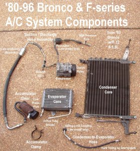
pic by Steve
○
Check for loose connector, or corroded terminals! etc. And:
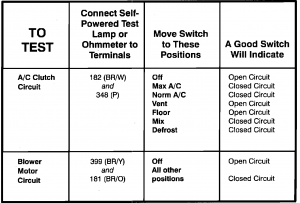

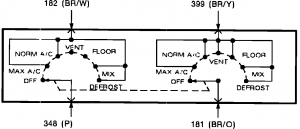
"
PINPOINT TEST G: A/C CLUTCH CYCLES RAPIDLY
G1 CHECK SYSTEM OPERATION
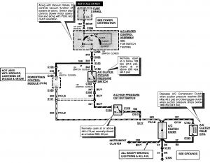
- Set function selector lever at an A/C position.
- Key to run.
Does A/C clutch engage?
| Yes | No |
|---|
| Clutch circuit OK. | GO to G2. |
G2 CHECK FOR VOLTAGE
- Check for voltage at circuit wire at the A/C cycling switch.
Is voltage present?
G3 BYPASS A/C CLUTCH CYCLING PRESSURE SWITCH
- Disconnect connector at A/C cycling switch.
- Jumper connector pins.
- A/C clutch should engage.
Does A/C clutch engage?
G4 CHECK HIGH PRESSURE CUT-OFF SWITCH FOR CONTINUITY
- Place multimeter in the OHMS position.
- Check A/C pressure cut-off switch for continuity.
Does A/C pressure cut-off switch test as having continuity?
| Yes | No |
|---|
| GO to G5. | REPLACE A/C pressure cut-off switch. GO to G1. |
G5 CHECK SYSTEM PRESSURE
- Connect gauge set and check system pressure.
Is pressure above 379 kPa (55 psi) (ambient temperature above 10°C [50°F])?
| Yes | No |
|---|
| REPLACE A/C cycling switch. Refer to Section 12-03A. GO to G6. | CHECK refrigerant system for leaks. REPAIR and CHARGE system as necessary. GO to G1. |
G6 CHECK A/C COMPRESSOR PRESSURE RELIEF VALVE
- Inspect area surrounding the A/C compressor pressure relief valve.
Are there signs of refrigerant venting (oily residue)?
| Yes | No |
|---|
| REPLACE A/C compressor pressure relief valve. GO to G1. | CHECK A/C system for leaks. REPAIR as necessary (if no leaks detected, CHARGE system). GO to G1. |
G7 CHECK VOLTAGE AT CLUTCH
- Check for voltage at A/C clutch field coil.
Is voltage present?
G8 CHECK CLUTCH GROUND
- Jumper ground terminal of A/C clutch field coil to ground.
Does A/C clutch engage?
| Yes | No |
|---|
| SERVICE open in ground wire. GO to G1. | REPLACE A/C clutch field coil. REFER to Section 12-03B. GO to G1."
●
|
Refrigerant Capacity .................... 2.0 lbs R134A
Refrigerant Oil System Capacity .................... 7.0 oz
●


