yo,
Try a Self Test for Diagnostic Trouble Codes (DTC)s by my pal, BroncoJoe19
http://broncozone.com/topic/14269-code-reader/page__pid__74587__mode__threaded
We can ruel out a few thAngs this way (DTC 67 Neutral Drive Switch (NDS) Circuit Open, etc.)
The engine temperature must be greater than 50° F for the Key On Engine Off (KOEO) Self-Test and greater than 180° F for the Key On Engine Running (KOER) Self-Test.
Run it around to heat the engine up and
shift thru all gears incl Reverse. Then turn off all accessories/lights, etc.
Make sure A/C is off and transmission is in Park (automatic) or in Neutral for a Manual & release clutch.
Do Key On Engine Off (KOEO) portion first.
Look Codes up in my broncolinks.com site using the new Search function.
And Post em here according to:
KOEO
&
KOER
=============
=======
Trouble Shooting, COMPREHENSIVE; "...from the AOD service manual..." Source: by duanemyhre
No 3-4 Upshift or Slipping 4TH Gear TSB 93-23-18 for 80-93 Bronco, Econoline & F 150
This TSB article is being republished because of the occasional need for the information it contains. Originally published as TSB 83-13-10 in June of 1983, this article is not easily locatable in many dealerships today; the model application has been updated. Also, The Service Manual contains this information.
ISSUE:
A no 3-4 upshift condition or a slipping 4th gear may result from
•Direct clutch checkball leaking
•Missing plug in end of output shaft
•Case bore wear
•Leakage at O/D band servo piston and/or case bore
•Seal leakage at 3-4 accumulator piston
•Blocked hydraulic circuit condition
•Improper valve body attaching bolt torque
•Leaking governor circuit
•Torque converter damper/hub malfunction
ACTION:
Road test, diagnose and repair the transmission as required. Refer to the following diagnostic and repair procedure for service details.
PRELIMINARY CHECKS/INFORMATION
1.Road test the vehicle to verify the customer complaint. A no 3-4 upshift is characterized by staying in 3rd gear. A slipping 4th gear is characterized by engine cut-loose on 3-4 upshifts and limited or no 4th gear drive capability.
2.Check TV rod/cable to see if bent, kinked or sticking. Repair or replace rod/cable as required.
3.Check TV linkage (could be misadjusted long). On older models, bent, sticking or misadjusted TV Linkage will not properly synchronize with the carburetor/throttle body lever at the time a 3-4 upshift should occur.
4.Check control pressure and throttle pressure to identify that they are within specifications. Use the following guide pressure specifications:
GUIDE PRESSURE SPECIFICATIONS *
GEAR RANGE IDLE--------------- W.O.T.
P,N,O/D,D,L 55-65 PSI---------- 175-205 PSI
Reverse 75-95 PSI--------------- 250-300 PSI
Pressures are typical with TV pressure adjusted to specification per Service Manual (approx 32 psi using gauge block). Refer to applicable model-year AUTOMATIC TRANSMISSION SPECIAL SPECIFICATIONS ISSUE for exact specifications, if required.
DIRECT CLUTCH PRESSURE TEST
Leakage in the direct clutch circuit is usually caused by a leaking checkball in the direct clutch piston. Replacement of the direct clutch piston will alleviate this condition. However, since other factors can be involved, the following additional checks/verifications will aid in making a comprehensive diagnosis of no 3-4 upshift and/or no 4th gear symptoms.
The direct clutch pressure test outlined below will diagnose a low pressure condition or leakage in the direct clutch circuit. A difference of 15 psi or more between direct clutch pressure and line pressure (read at the forward clutch pressure tap) will prevent a 3-4 upshift.
1.Attach 0-300 psi (0-2068 kPa) pressure gauges to the forward clutch and to the direct clutch pressure tap, Figure 1.
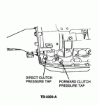
Figure 1 - Article 93-23-18
a.Gauge accuracy must be capable of distinguishing a 15 psi (110 kPa) difference. (If this test is done in conjunction with a control pressure test, pressure gauges will be attached to all pressure taps).
b.Connect sufficient flexible hose to be able to read the gauges inside the vehicle.
CAUTION: PRESSURE GAUGES AFFECT THE SHIFT QUALITY OF THE TRANSMISSION. DO NOT ACCELERATE OR DECELERATE RAPIDLY WHILE PRESSURE GAUGES ARE ATTACHED. TRANSMISSION FAILURE MAY RESULT.
2.Drive the vehicle. When pressure is applied to the direct clutch, note the difference between line pressure (read at the forward clutch pressure tap) and direct clutch pressure (read at the direct clutch pressure tap).
3.If the difference in pressure is less than 15 psi (110 kPa), the direct clutch circuit is OK.
4.If the difference is greater than 15 psi (110 kPa), there could be a leak in the direct clutch pressure circuit.
a.The gauges on the forward and direct clutch pressure taps can be switched to confirm that gauge calibration difference is not the cause.
b.If a 15+ psi (110 kPa) pressure differential can be confirmed, proceed to the "DIAGNOSTIC PROCEDURE NO. 1" (leakage indicated), or to "DIAGNOSTIC PROCEDURE NO. 2" (slips in 4th), if applicable.
c.If a 15+ psi (110 kPa) pressure differential cannot be confirmed, proceed to "DIAGNOSTIC PROCEDURE NO. 3" (no leakage indicated).
DIAGNOSTIC PROCEDURE NO. 1 - NO 3-4 UPSHIFT WITH DIRECT CLUTCH PRESSURE DIFFERENCE GREATER THAN 15 PSI (110 kPa) - (indicates leakage in direct clutch circuit)
NOTE: BURNT DIRECT CLUTCH PLATES WILL HELP TO CONFIRM LEAKAGE IN THE DIRECT CLUTCH CIRCUIT. REPLACING ONLY THE PLATES AND NOT FINDING THE CAUSE COULD RESULT IN A REPEAT REPAIR.
1.Check valve body bolt torque. Correct torque is 9-11 N-m (80-97 lb-in).
2.Remove the valve body and check to see if main control gasket is blocking an orifice.
3.Check valve body-to-case mating surfaces for nicks or porosity.
4.Check the direct clutch piston check ball for leakage (inspect check ball for freedom of movement). Improper seating of check ball will cause leakage:
a.Turn piston upside down (flat side of piston facing you) allowing the check ball to seat in the piston.
b.Pour a small quantity of solvent over the check ball. If solvent drops past the check ball, replace the piston.
5.Inspect the output shaft feed passages and the cup plug for leakage.
a.Apply 5-10 psi (34-69 kPa) air to the output shaft feed passages, Figure 2.
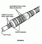
Figure 2 - Article 93-23-18
b.If air comes out of the wrong feed passage, replace the output shaft.
6.Check the direct clutch piston seal rings (inner and outer) for leakage.
7.Check all direct clutch output shaft seals for freedom of movement and for metal shavings and burrs between the seal and the output shaft, Figure 2
8.Check the direct clutch cylinder for groove marks on the inner ID of the drum, Figure 3.
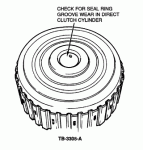
Figure 3 - Article 93-23-18
a.Groove marks indicate that the small cast iron rings are turning with the output shaft and grooving the cylinder.
b.Groove marks may also be caused by contamination or burrs in the output shaft seal ring grooves, causing the seal rings to turn with the output shaft.
c.Check the seal ring grooves carefully. replace the output shaft, seal rings and/or cylinder as required, and/or replace the case if the output shaft seal bore is grooved.
DIAGNOSTIC PROCEDURE NO. 2 - SLIPPING IN 4TH GEAR
NOTE: A BURNT OVERDRIVE BAND WILL HELP TO CONFIRM LEAKAGE IN THE OVERDRIVE CIRCUIT. REPLACING ONLY THE OVERDRIVE BAND WITHOUT FINDING THE CAUSE WILL RESULT IN A REPEAT REPAIR. IF THE OVERDRIVE BAND IS NOT BURNT, THE TORQUE CONVERTER DAMPER/HUB WELD MAY BE SUSPECT.
1.Check the overdrive servo cover O-rings and servo piston seal for possible leakage. Replace the O-rings and seal if leakage is evident.
2.Make sure that the overdrive servo cover is not porous:
a.Coat cover with fluid.
b.Apply air to overdrive servo apply passage using Servo Piston Remover T80L-77030-B or Transmission Test Plate T82L-7006-A.
c.Observe to see if air bubbles are present on overdrive servo cover.
3.Check the overdrive servo case apply passage to see if it is blocked (air pressure test). Replace the case if required.
4.Confirm that the overdrive band is seated correctly to the anchor pin.
5.Check the torque converter for damper/hub weld failure by performing the weld check procedure outlined in the Service Manual:
a.Use Torque Converter Checking Tool T83L-7902-A.
b.Replace the torque converter if shaft turns more than two (2) degrees, or if there is a grinding noise while applying 68 N-m (50 lb-ft) of torque.
6.Check splines on both ends of the direct drive shaft and in the direct clutch cylinder for damage/wear.
DIAGNOSTIC PROCEDURE NO. 3 - NO 3-4 UPSHIFT WITH DIRECT CLUTCH PRESSURE DIFFERENCE LESS THAN 15 PSI (110 kPa) - (indicates no leakage in direct clutch circuit)
1.Clean the valve body:
a.Check for a "sticking" condition at the following valves:
•Overdrive servo regulator valve
•3-4 shift valve
•3-4 TV modulator valve
•Orifice control valve
b.If any valves are sticking and cannot be free, replace the valve body.
2.Reduce the valve body bolt torque to minimum specification, i.e. 9 N-m (80 lb-in).
3.Check the fit of the governor counterweight on the output shaft. If the fit is sloppy, replace the counterweight.
4.Check the governor-to-output shaft retaining ring to make sure it is properly seated on the output shaft; service as required.
5.Check the last two large seal rings on the output shaft (#9, #10), Figure 2.
a.The seal rings should move freely on the output shaft.
b.Check for metal or other contamination or burrs between the seal and the output shaft; replace the seals and/or output shaft as required.
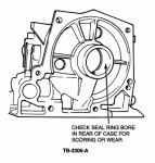
6.Check the seal ring bore at the rear of the case for scoring. Light scoring is permissable, but deep grooving indicates case wear. Replace the case if deep grooving is found, Figure 4.
