crazy speed-o crazy shifting ,need ideas

Disclaimer: Links on this page pointing to Amazon, eBay and other sites may include affiliate code. If you click them and make a purchase, we may earn a small commission.

azrick

New member
Joined
Aug 2, 2011
Messages
6
Reaction score
0
Location
Phoenix, AZ
My 94 bronco sort of suddenly, started shifting up and down, the speed-o was jumping up and down. I put a tester on it and pulled codes 334 , 453 , 637 does anyone know what these are and maybe a solution? truck is in peices in driveway and need it for work. thanks


miesk5

96 Bronco 5.0
Staff member
Moderator
Joined
Oct 18, 2005
Messages
9,078
Reaction score
1,037
Location
Floating in the Pacific
yo Rick,

WELCOME!

No 453 Code; re-do test; am guessing it 452 Vehicle Speed Sensor (VSS) problem & that can cause the problem

Check Fuses 8 & 18 in Cab fuse block (lower left of dash by driver's left knee)

If no 12 v on Supply Side of each; look in Power Distribution Box (Located under the hood on the drivers side fenderwell, on driver's side of the air cleaner housing)

and check **** FUSES J & S

fuses94gas.jpg

Diagram in a 94

This problem could be caused by a # of thangs;

bad vehicle speed sensor (VSS) (also called ABS,, DSS sensor) sensor on da 8.8 (rear differential)/ or

Connector/corroded wires inside connector;

or cruddy/damaged tone ring in the 8.8.

bad wiring/shorts /connectors from VSS at firewall, at 4WABS Module and /or at PSOM and then onto the PCM

bad 4WABS Module - It is located below ws wiper fluid/coolant recovery tank. So, the connector can be corroded by leaking fluid

bad PSOM (Speedo)

Speed Input Signal Test @ PSOM in 93-96 Bronco; "...NOTE: Only wiring harness end of connector is to be probed. * Connect Rotunda Digital Volt-Ohmmeter 014-00407 or equivalent to Pin 4 (speed in ) and Pin 5 (speed in -). * Does the voltage increase smoothly and continuously from 0 to approximately 3.5 volts as vehicle speed increases from 0 to 48 km/h (0 to 30 mph)? OR: If available, a frequency counter may be connected to Pin 4 (Speed in ) and Pin 5 (Speed in -). Does the displayed frequency of the signal increase smoothly and continuously from 0 to approximately 667 Hz at approximately 48 km/h (30 mph)? OR: * If neither a voltmeter nor frequency counter is available, vehicle speed control may be used as a good indicator. If it works normally, then the speedometer module is at least receiving a speed input signal and the wiring and sensor & tone ring can be assumed to be good.

This is tuff to do; suggest using str8 pins to back probe the connector

My 96's same symptoms were erratic until the 4WABS Module's microprocessors finally burnt-out. I had one go bad and 2 yard Modules were also bad; so I jumpered the Module out as Steve & Turbo Ghost describes below.

To bypass the 4WABS module @ it's harness's connector & feed the ABS signal directly to the PSOM,

Disconnect module (under coolant recovery /ws washer tank) & in connector, jumper LG/Bk to LG/Y, and R/Pk to O/LB..."

pic of the connector and jumpers by Turbo Ghost

Then run it around; if back to normal then permanently jumper it out or try to find a good Module at a yard.

ABS560102-TOP-P01.jpg


Re-Man Modules are avail by Raybestos # ABS560102

Tone Ring Inspection; "Take off the rear diff cover. Check the Ring Tone gear. It is located on the left hand side of the ring gear. Look to see if any of the teeth have been notched (from debris floating around in the diff.) Usually a spider gear. If the ring tone gear has been notched, it will need to be replaced to fix your speedo reading. Jack it up and rotate the tires to look for the teeth to be notched/broken/bent..."

Source: by Bighibbi at FSB

more VSS info in my site @ http://www.broncolinks.com/index.php?index=139

More 4WABS Info, Connector Location and pin out diagrams etc in my site @ http://www.broncolinks.com/index.php?index=240

=====

DTC 334 EGR (EVP) closed valve voltage higher than expected; "...Failed sensor, & as by rla2005 (Randy) wrote; carbon between EGR pintle valve and seat holding the valve off its seat. Remove the EGR valve and clean it with carbon remover. Prior to re-installing see if you can blow air through the ****** side of the EGR by mouth. the egr is not closing properly which can cause detonation. remove the egr and clean off any carbon built up on it with carb cleaner and a brush if necessary. The EGR Valve Position (EVP) Sensor used exclusively by Ford, can be the cause of driveability problems without ever setting any trouble codes. The relationship between the EVP sensor and the EGR valve is important to understand. Either one being out of spec can cause similar symptoms. Understanding this relationship will help you to diagnose uncoded driveability problems like stumbles, hesitations, rough idles and stalling..." read more

Source: by rla2005 (Randy) & miesk5

DTC 334: CHECK FOR DTC 558 in Key On Engine Off (KOEO) or Engine Running (KOER) Self-Test indicates the EGR valve and/or EGR Valve Position (EVP) sensor may not be fully seated in the closed position. The EVP sensor voltage is greater than the closed limit voltage of 0.67 volt. "...Breakout box pin numbers correspond directly to EEC connector pin numbers. Because of the preload on the installed EVP sensor, it is difficult to determine whether the EGR valve is seated or the EVP sensor is in contact with the EGR valve stem. Possible causes: Poor continuity in EVP sensor harness. Non-seated EGR valve. Damaged EGR valve. Damaged EVP sensor. Damaged EVR solenoid. Damaged Powertrain Control Module (PCM). Key off. Is DTC 558 present in KOEO Self-Test? Yes GO to DN10. No GO to DN21. DN21 RERUN KOEO AND KOER SELF-TEST WITH EGR VACUUM DISCONNECTED. Disconnect vacuum hose from EGR valve and plug hose. Rerun KOEO and KOER Self-Test. Is DTC 334 present? Yes GO to DN22. No CHECK EVR solenoid for obstructions. SERVICE as necessary. If OK, REPLACE EVR solenoid. RECONNECT all vacuum hoses. RERUN Quick TestDN22 CHECK EVP SENSOR AND EGR VALVE OPERATION Key off. Disconnect EVP sensor. lnspect the connectors on harness and sensor for damaged pins, corrosion, loose wires, etc. Service as necessary. Remove vacuum line from EGR valve. Exercise EGR valve by applying and releasing vacuum with a vacuum pump. Reconnect vacuum line to EGR valve and electrical connector to EVP sensor. Rerun KOEO and KOER Self-Test. Is DTC 334 still present? Yes GO to DN23. No The original DTC 334 was the result of poor continuity at the EVP sensor connector or binding of the EGR valve stem by contaminants. Testing complete. DN23 CHECK EVP SIGNAL VOLTAGE; Key off. Disconnect Powertrain Control Module (PCM). Inspect for damaged or pushed out pins, corrosion, loose wires, etc. Service as necessary. Install breakout box and connect PCM to breakout box. Key on, engine off. Measure voltage between Test Pin 27 and Test Pin 46 at the breakout box. Is voltage greater than 0.67 volts? Yes GO to DN24. No REPLACE PCM. REMOVE breakout box. RERUN Quick Test. DN24 FAULT ISOLATION CHECK; The fault has been isolated to the EGR valve or EVP sensor. Due to the nature of this particular fault, the EGR valve is suspect because of its vulnerability to contamination and carbon build-up from the exhaust flow. If the engine runs rough at idle, this is a good indication that the EGR valve is not fully seated rather than a worn or damaged sensor. Remove the EGR valve and EVP sensor. Inpect both components for contamination, unusual wear, carbon deposits, binding and other damage. Service as necessary. (Use Rotunda EGR Valve Cleaner 021-80056 or equivalent if needed.). Reinstall EGR valve and EVP assembly and run KOEO and KOER Self-Test. Is DTC 334 still present? Yes REPLACE EGR valve. REMOVE breakout box. RERUN Quick Test. If DTC is still present, REPLACE EVP sensor. No The original DTC 334 was the result of EGR valve contamination, binding or a worn or damaged EVP sensor. Testing complete..."

Source: by Ford

=====

637 (O,M) TOT sensor is/was high or open

DTC 637 - TOT sensor circuit above maximum voltage possible causes: Damaged TOT sensor. Open harness circuit(s). Damaged processor. or the transmission was overheated. The transmission fluid temperature sensor is located on the solenoid body assembly in the transmission sump. It is a temperature-sensitive device called a thermistor. The resistance value of the transmission fluid temperature sensor will vary with temperature change. The powertrain control module monitors voltage across the transmission fluid temperature sensor to determine the temperature of the transmission fluid. The powertrain control module uses this signal to determine whether a cold start shift schedule is necessary. The cold start shift schedule lowers shift speeds to allow for the reduced performance of cold engine operation. The powertrain control module also uses the transmission fluid temperature sensor input to adjust electronic pressure control pressure for temperature effects and inhibit torque converter clutch operation during the warm-up period. Symptoms: Torque converter clutch and stabilized shift schedule happens too soon after a cold start. Codes P1783 or 657 indicate transmission fluid temperature exceeds 132°C (270° F), results in increased EPC pressure and torque converter clutch engagement. May flash transmission control indicator lamp. Diagnostic Trouble Codes: 636, 637, 638, 657, P0712, P0713, P1711, P1783.

Source: by Ford

Check to make sure transmission harness connector is fully seated, terminals are fully engaged in connector and in good condition before proceeding.

Disconnect transmission connector.

CAUTION: Remove heat shield from transmission before removing connector. Remove solenoid body connector by pushing on center tab and pulling on wiring harness. Do not attempt to pry tab with a screwdriver. Reinstall heat shield after service.

Using a mirror, inspect both ends of connector for damaged or pushed out pins, corrosion, loose wires, and missing or damaged seals.

I have more tests if you need them.

==============

 
OP
OP
A

azrick

New member
Joined
Aug 2, 2011
Messages
6
Reaction score
0
Location
Phoenix, AZ
yo Rick,

WELCOME!

No 453 Code; re-do test; am guessing it 452 Vehicle Speed Sensor (VSS) problem & that can cause the problem[/


Check Fuses 8 & 18 in Cab fuse block (lower left of dash by driver's left knee)

If no 12 v on Supply Side of each; look in Power Distribution Box (Located under the hood on the drivers side fenderwell, on driver's side of the air cleaner housing)

and check **** FUSES J & S

fuses94gas.jpg

Diagram in a 94


This problem could be caused by a # of thangs;

bad vehicle speed sensor (VSS) (also called ABS,, DSS sensor) sensor on da 8.8 (rear differential)/ or

Connector/corroded wires inside connector;

or cruddy/damaged tone ring in the 8.8.

bad wiring/shorts /connectors from VSS at firewall, at 4WABS Module and /or at PSOM and then onto the PCM

bad 4WABS Module - It is located below ws wiper fluid/coolant recovery tank. So, the connector can be corroded by leaking fluid

bad PSOM (Speedo)


Speed Input Signal Test @ PSOM in 93-96 Bronco; "...NOTE: Only wiring harness end of connector is to be probed. * Connect Rotunda Digital Volt-Ohmmeter 014-00407 or equivalent to Pin 4 (speed in ) and Pin 5 (speed in -). * Does the voltage increase smoothly and continuously from 0 to approximately 3.5 volts as vehicle speed increases from 0 to 48 km/h (0 to 30 mph)? OR: If available, a frequency counter may be connected to Pin 4 (Speed in ) and Pin 5 (Speed in -). Does the displayed frequency of the signal increase smoothly and continuously from 0 to approximately 667 Hz at approximately 48 km/h (30 mph)? OR: * If neither a voltmeter nor frequency counter is available, vehicle speed control may be used as a good indicator. If it works normally, then the speedometer module is at least receiving a speed input signal and the wiring and sensor & tone ring can be assumed to be good.

This is tuff to do; suggest using str8 pins to back probe the connector


My 96's same symptoms were erratic until the 4WABS Module's microprocessors finally burnt-out. I had one go bad and 2 yard Modules were also bad; so I jumpered the Module out as Steve & Turbo Ghost describes below.


To bypass the 4WABS module @ it's harness's connector & feed the ABS signal directly to the PSOM,

Disconnect module (under coolant recovery /ws washer tank) & in connector, jumper LG/Bk to LG/Y, and R/Pk to O/LB..."


pic of the connector and jumpers by Turbo Ghost

Then run it around; if back to normal then permanently jumper it out or try to find a good Module at a yard.

ABS560102-TOP-P01.jpg


Re-Man Modules are avail by Raybestos # ABS560102


Tone Ring Inspection; "Take off the rear diff cover. Check the Ring Tone gear. It is located on the left hand side of the ring gear. Look to see if any of the teeth have been notched (from debris floating around in the diff.) Usually a spider gear. If the ring tone gear has been notched, it will need to be replaced to fix your speedo reading. Jack it up and rotate the tires to look for the teeth to be notched/broken/bent..."

Source: by Bighibbi at FSB


more VSS info in my site @ http://www.broncolinks.com/index.php?index=139


More 4WABS Info, Connector Location and pin out diagrams etc in my site @ http://www.broncolinks.com/index.php?index=240


=====


DTC 334 EGR (EVP) closed valve voltage higher than expected; "...Failed sensor, & as by rla2005 (Randy) wrote; carbon between EGR pintle valve and seat holding the valve off its seat. Remove the EGR valve and clean it with carbon remover. Prior to re-installing see if you can blow air through the ****** side of the EGR by mouth. the egr is not closing properly which can cause detonation. remove the egr and clean off any carbon built up on it with carb cleaner and a brush if necessary. The EGR Valve Position (EVP) Sensor used exclusively by Ford, can be the cause of driveability problems without ever setting any trouble codes. The relationship between the EVP sensor and the EGR valve is important to understand. Either one being out of spec can cause similar symptoms. Understanding this relationship will help you to diagnose uncoded driveability problems like stumbles, hesitations, rough idles and stalling..." read more

Source: by rla2005 (Randy) & miesk5


DTC 334: CHECK FOR DTC 558 in Key On Engine Off (KOEO) or Engine Running (KOER) Self-Test indicates the EGR valve and/or EGR Valve Position (EVP) sensor may not be fully seated in the closed position. The EVP sensor voltage is greater than the closed limit voltage of 0.67 volt. "...Breakout box pin numbers correspond directly to EEC connector pin numbers. Because of the preload on the installed EVP sensor, it is difficult to determine whether the EGR valve is seated or the EVP sensor is in contact with the EGR valve stem. Possible causes: Poor continuity in EVP sensor harness. Non-seated EGR valve. Damaged EGR valve. Damaged EVP sensor. Damaged EVR solenoid. Damaged Powertrain Control Module (PCM). Key off. Is DTC 558 present in KOEO Self-Test? Yes GO to DN10. No GO to DN21. DN21 RERUN KOEO AND KOER SELF-TEST WITH EGR VACUUM DISCONNECTED. Disconnect vacuum hose from EGR valve and plug hose. Rerun KOEO and KOER Self-Test. Is DTC 334 present? Yes GO to DN22. No CHECK EVR solenoid for obstructions. SERVICE as necessary. If OK, REPLACE EVR solenoid. RECONNECT all vacuum hoses. RERUN Quick TestDN22 CHECK EVP SENSOR AND EGR VALVE OPERATION Key off. Disconnect EVP sensor. lnspect the connectors on harness and sensor for damaged pins, corrosion, loose wires, etc. Service as necessary. Remove vacuum line from EGR valve. Exercise EGR valve by applying and releasing vacuum with a vacuum pump. Reconnect vacuum line to EGR valve and electrical connector to EVP sensor. Rerun KOEO and KOER Self-Test. Is DTC 334 still present? Yes GO to DN23. No The original DTC 334 was the result of poor continuity at the EVP sensor connector or binding of the EGR valve stem by contaminants. Testing complete. DN23 CHECK EVP SIGNAL VOLTAGE; Key off. Disconnect Powertrain Control Module (PCM). Inspect for damaged or pushed out pins, corrosion, loose wires, etc. Service as necessary. Install breakout box and connect PCM to breakout box. Key on, engine off. Measure voltage between Test Pin 27 and Test Pin 46 at the breakout box. Is voltage greater than 0.67 volts? Yes GO to DN24. No REPLACE PCM. REMOVE breakout box. RERUN Quick Test. DN24 FAULT ISOLATION CHECK; The fault has been isolated to the EGR valve or EVP sensor. Due to the nature of this particular fault, the EGR valve is suspect because of its vulnerability to contamination and carbon build-up from the exhaust flow. If the engine runs rough at idle, this is a good indication that the EGR valve is not fully seated rather than a worn or damaged sensor. Remove the EGR valve and EVP sensor. Inpect both components for contamination, unusual wear, carbon deposits, binding and other damage. Service as necessary. (Use Rotunda EGR Valve Cleaner 021-80056 or equivalent if needed.). Reinstall EGR valve and EVP assembly and run KOEO and KOER Self-Test. Is DTC 334 still present? Yes REPLACE EGR valve. REMOVE breakout box. RERUN Quick Test. If DTC is still present, REPLACE EVP sensor. No The original DTC 334 was the result of EGR valve contamination, binding or a worn or damaged EVP sensor. Testing complete..."

Source: by Ford


=====


637 (O,M) TOT sensor is/was high or open

DTC 637 - TOT sensor circuit above maximum voltage possible causes: Damaged TOT sensor. Open harness circuit(s). Damaged processor. or the transmission was overheated. The transmission fluid temperature sensor is located on the solenoid body assembly in the transmission sump. It is a temperature-sensitive device called a thermistor. The resistance value of the transmission fluid temperature sensor will vary with temperature change. The powertrain control module monitors voltage across the transmission fluid temperature sensor to determine the temperature of the transmission fluid. The powertrain control module uses this signal to determine whether a cold start shift schedule is necessary. The cold start shift schedule lowers shift speeds to allow for the reduced performance of cold engine operation. The powertrain control module also uses the transmission fluid temperature sensor input to adjust electronic pressure control pressure for temperature effects and inhibit torque converter clutch operation during the warm-up period. Symptoms: Torque converter clutch and stabilized shift schedule happens too soon after a cold start. Codes P1783 or 657 indicate transmission fluid temperature exceeds 132°C (270° F), results in increased EPC pressure and torque converter clutch engagement. May flash transmission control indicator lamp. Diagnostic Trouble Codes: 636, 637, 638, 657, P0712, P0713, P1711, P1783.

Source: by Ford

Check to make sure transmission harness connector is fully seated, terminals are fully engaged in connector and in good condition before proceeding.

Disconnect transmission connector.

CAUTION: Remove heat shield from transmission before removing connector. Remove solenoid body connector by pushing on center tab and pulling on wiring harness. Do not attempt to pry tab with a screwdriver. Reinstall heat shield after service.


Using a mirror, inspect both ends of connector for damaged or pushed out pins, corrosion, loose wires, and missing or damaged seals.

I have more tests if you need them.

==============


Ok Thanks for that , My VSS pick up in the diff was damaged, almost like something hit it ? just put a new one in for now till I have time to take the diff apart.. Also I found my # 10 fuse the 4 amp. the lbr/r wire was melted all the way to the radio, but the others it connected to seemed not melted , so I replaced that. That's probably why I never had dash lights. ,also looks like someone may have disconnected the air bag.. But the cruise has never worked either. There is a black wire about 14 gauge that's been cut between the column and the steering wheel ? do you think this is a ground or ?? but might it have anything to do with my cruise ?

Thanks I appreciate it.. Going to finish putting dash back together


miesk5

96 Bronco 5.0
Staff member
Moderator
Joined
Oct 18, 2005
Messages
9,078
Reaction score
1,037
Location
Floating in the Pacific
yo,

Don't take the diff cover off in just the VSS sensor itself was externally damaged.

Did new VSS solve the main issues?

===========

Cruise Control

First, there is an active recall for the Cruise Control;

Recall for 93-96 Bronco, 94-02 F-150, 97-02 Expedition & 98-02 Lincoln Navigators; NHTSA Campaign id number: 05v388000, 07v336000 & 05v017000; recall date Jan 27, 2005 & update; (search for 07v336000 & 05v017000 in "safety recalls) on certain sport utility vehicles and pickup trucks, the speed control deactivation switch may overheat, smoke, or burn this condition could lead to a fire. Fires have occurred while the vehicles were parked with the ignition 'off.' as an interim repair, owners will be instructed to return their vehicles to their dealers to have the speed control deactivation switch disconnected. As soon as replacement parts are available (early April 2005), owners will be instructed to return to the dealers for installation of a new switch free of charge. Owners may contact ford at 1-800-392-3673. (note: also see recalls 05v388 and 06v286) Ford recall no. 05s28. Customers may also contact the National Highway Traffic Safety Administration's vehicle safety hotline at 1-888-327-4236 (TTY 1-800-424-9153), OR GO TO HTTP://WWW.SAFERCAR.GOV

Many owners have said that their local dealer said the recall was "over" and they would be charged for the wiring and switch changes. BUT "took it to the dealer today and got a new one installed free ." 12 April 2011 Source: by tr21triton.

and

"...I have a 95 Bronco and back in feb.-11- 2010 my rig's master cylinder's Speed Control Deactivation Switch connection caught fire, this is what the recall "speed control system" is and the recall is still on going. Just go to www.fordowner.com to find out about recalls. After contacting Fordowner.com and filing a claim they passed it on to the claims group @ FORD to be reviewed. Once the group reviewed my claim then someone got in touch with me, I have to mail copys of my title, bill of sale, ect. and copy's of photos of the damage to her. She said that the dealer dose not have parts for vehicles 10 years and older so I have to get my local shop to replace the master cylinder and the wires that were effected by the break fluid and their labor cast, she will cut me/the shop a check and then after the work is done then the dealer will look it over to make sure the truck and the work is up-to-date. All this to fix something that at most costs $200. ***..."

Source: by Belafox

=======

lbl/r

There is a R/LB wire from PSOM to Cruise Servo/Amplifier Assy.

And a R/LB wire from Ignition Switch to through the Manual Lever Position Sensor (MLPS) on E4OD, Or clutch safety switch on M5OD to starter relay coil.

Nothing from;

Air Bag ckt (clock spring, etc.)

Multi-Function Switch (MFS)- wiper/washer; Hazard, Turn, High & Low Headlight Dimmer, Flash-to-Pass & Brake Light CKTs are a Feed-Through Circuit in Multi-Function Switch (MFS)

Horn Switch

What other components are in strg col that you can check the wiring diagrams for this and the black wire other than those?

I have to roll soon, so take a look at various wiring diagram in my site under the applicable component or system

Start with Electrical,

=====

Black Wire

There is B wire from Ignition Switch through Splice S202 (in wiring harness) to Ground (G201) that is behind driver's kick panel; for all the windows, courtesy lights, instrument cluster, lighter sockets, blower, & horn switch

Nothing from;

Air Bag ckt

Cruise ckt

Horn

Multi-Function Switch (MFS)- wiper/washer; Hazard, Turn, High & Low Headlight Dimmer, Flash-to-Pass & Brake Light CKTs are a Feed-Through Circuit in Multi-Function Switch (MFS)

--------

 
OP
OP
A

azrick

New member
Joined
Aug 2, 2011
Messages
6
Reaction score
0
Location
Phoenix, AZ
I'll check out those wiring diagrams, thanks.. So first time I've seen dash lights, after fixing that melted wire. Speed-O still acting little crazy , but shifting a bit better. The tranny still sounds like it's sluggish or sort of louder then normal, likes it's reving a bit more ? I'll go back and look were you mentioned that temp. solenoid .. Again you've been a great help...


miesk5

96 Bronco 5.0
Staff member
Moderator
Joined
Oct 18, 2005
Messages
9,078
Reaction score
1,037
Location
Floating in the Pacific
yo,

Was the VSS sensor externally damaged?

Or,

was the interanal section damaged? if so, then do pull diff cover and inspect

On the TOT sensor; Ford isn't specific on whether the self test should be done at normal op temp for the TOT.

But since the Bronco is down for awhile, may as well ck it out

 
OP
OP
A

azrick

New member
Joined
Aug 2, 2011
Messages
6
Reaction score
0
Location
Phoenix, AZ
Just want to start off by thanking you for all your info. It has defiantly saved me some time and money.

The VSS sensor had a dent on the bottom (internal section ) and looks like that caused it to crack at that point.. I did the KOEO test and got 111 twice, then the KOER and got 312, and 412. I think I was off when i did the switch test and the WOT. I preformed the test again and got 111, 111.

Since I've owned the vehicle the dash lights have not worked, no horn, no remote key pads, so the alarm light flashes when the key is not on,( most likely why the horn is disconnected), and the ABS light was almost always on, and cruise has never worked. The speed-o has always worked. The only problems I had were it shutting down on me. Everyone wanted me to replace the fuel pump. I just didn't feel that was it. Read some Posts here and replaced the TFI module, among other things to complete a pretty full tune up. That pretty much took care of that, It's run great since then, - the first issues I mentioned, I had just corrected the wiring issue the other day. Well now mostly great, Dash lights are wonderful. Just the speed-o still jumps back and forth like 10 mph. The tranny also sounds like it's over revving still and shifts slow from the line. Now the truck has overheated in the past, but I flushed out the radiator, and it's been running fine till now. Seems this issue is causing it to run hotter also.

Well think that gives you some insight, so I was wondering if the first thing I should do is open the diff. ? if that ring is chipped, Could that be the main cause of these issues ? Because that TOT sensor really sounds like it could be causing some of this. Should I try the self test at this point? Just wanted to get your input, it's like 113 and was hoping to not wast too much time out there... ya know?

Thanks again


miesk5

96 Bronco 5.0
Staff member
Moderator
Joined
Oct 18, 2005
Messages
9,078
Reaction score
1,037
Location
Floating in the Pacific
yo,

Good on the self test pass codes so iggie that unless you get a Check Engine Light (CEL) or have other issues.

open the diff. & check for tone ring (Ford calls it the exciter ring at times) damage; if none, clean as much as possible.

next is:

PSOM Pointer Waiver TSB 96-21-11 by Ford for 92-96

Programmable Speedometer/Odometer Module Pointer Waiver Article No. 96-21-11

ISSUE: The speedometer needle may waver and/or a light surge may occur on some vehicles when speed control is used

at highway speeds between 80-113 km/h (50-70 mph). This may be due to slight dents/chips in either the exciter ring

or the Vehicle Speed Sensor (VSS) and air gaps between the VSS and the exciter ring.

ACTION: Replace the Programmable Speedometer/Odometer Module (PSOM) if required. New PSOM's come with increased immunity to system variability. Refer to the following Diagnostic Procedure for details.

DIAGNOSTIC PROCEDURE

BRONCO/F-SERIES - Perform normal PSOM diagnostics per Pinpoint Tests "H" and "J" of the 1996 F-Series/Bronco

Body/Chassis Service Manual, Pages 13-01-30 through 13-01-32 and Pinpoint "B" of the 1996 Powertrain/Drivetrain Service Manual,

Page 10-03-11.

1. Any slight dents, chips, etc., in either the exciter ring or VSS will create needle waver. Measure air gap between the VSS and exciter ring. It should be 0.38-0.51 mm (0.015-0.020").

2. Check exciter ring runout per the same ring gear backface runout procedure of the appropriate model 1996

Powertrain/Drivetrain Service Manual, Section 05-00. Make sure the exciter ring is mounted correctly to the

ring gear. If runout is more than 0.1 mm (0.004"), perform the differential runout check per the procedure in the

appropriate model 1996 Powertrain/Drivetrain Service Manual, Section 05-02A or 05-02D, to find cause and repair as needed.

3. If all items listed above check good, replace the Instrument Cluster Assembly. Obtain the correct service part number from the Parts Catalogue

and then contact the Electronic Odometer Exchange Center at (800) 259-9700 for U.S. Dealers and (800) 663-9974 for Canadian Dealers.

NOTE: DEALERSHIP MUST TELL THE ODOMETER EXCHANGE CENTER THAT YOU NEED A PSOM3 LEVEL CLUSTER FOR A SPEEDOMETER NEEDLE WAVER CONCERN.

OTHER APPLICABLE ARTICLES: NONE

WARRANTY STATUS: Eligible Under The Provisions Of Bumper To Bumper Warranty Coverage

Bronco 962111B Replace Programmable 0.7 Hr.

BASIC PART NO. CODE 10849 06

read more in my site @ http://home.comcast.net/~miesk5/technical_service_bulletins.htm#technical_service_bulletins.htm

I wouldn't replace cluster yet if tone ring looks ok. Can do the other tests to rule out bad wiring at connectors, etc.

If tone ring is damaged;

Tone Ring (also called Exciter Ring) Source & pic; Item #32392; "...This is the ring inside the axle housing that the speed/abs sensor reads off of. 8.5" outside diameter, 108 Teeth..."

88EXCTRTONERING.JPG
$38.00

and Bronco Zone members ger a discount!

Jeff at the Bronco Graveyard has offered a 2% discount to members of The BroncoZone for on line orders. To get your discount, enter the discount code BZMEMBER. Also you must include your BroncoZone User Name with the order

Source: by Jeff's Bronco Graveyard

Tone Ring Removal/Installation (also called Speed Sensor Ring) w/additional info incorporated by Steve83

Source: by Dave's Bronc 90

1- Remove carrier cross pin bolt, and then the pin.

2- Push in each axle to expose the c-clip, then remove the c-clip and pull the axle out of the carrier.

3- Mark the orientation of the bearing caps... The bearing caps are marked for direction when they're cast. Remove bearing caps.

4- Pull out the carrier, taking extreme caution to not mix up the bearing races and shim packs. They must go back in exactly as they are in right now, or you'll have to do a full gear set up when you put it back in.

5- Don't remove anything from the carrier that doesn't fall off.

6- Find the internal locating tooth on the tone ring, then spin the carrier 180° & pry the damaged tone ring away from the ring gear. When it comes off the carrier, push it to disengage the locating tooth.

7- Hook the tooth of the new tone ring into the pocket on the lip of the carrier behind the ring gear, and tap it on.

8- Put the carrier back in taking care to put the bearing races and shim packs back in their original positions.

9- Reinstall the bearing caps in their original positions, use a lot of red LocTite and torque to spec.

10- Slide the axles back in and reinstall the c-clips.

11- Reinstall the cross pin & a NEW bolt, torquing to spec.

That's pretty much it. It's not hard to do at all, you can do it in less than a half hour.

additional comment by jopes; "...If you heat the tone ring with torches or a oven, there is no need to tap it on. you can set it on with ease. Those tone rings are so thin you can break them if you look at them funny..."

 
Last edited by a moderator:
OP
OP
A

azrick

New member
Joined
Aug 2, 2011
Messages
6
Reaction score
0
Location
Phoenix, AZ
P1010766re.jpgP1010763rs.jpgP1010766re.jpg

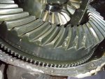
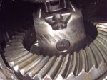
O.K. The tone ring defiantly is nicked up, no missing teeth though. Now the Marks on the carrier, from the pinion gear? What would cause this? And nice chipped teeth on the Ring gear.

P1010760rs.jpg


miesk5

96 Bronco 5.0
Staff member
Moderator
Joined
Oct 18, 2005
Messages
9,078
Reaction score
1,037
Location
Floating in the Pacific
yo,

Oh well, some will say clean up sharp edges & run it until it breaks, but since it's apart check for a yard diff and inspect. All prob. caused by excessive heat.

I would replace the diff even though I hate spending if I can find a work-around.


Members online

Forum statistics

Threads
22,667
Messages
136,905
Members
25,368
Latest member
digs
Top