yo,
this is from my 96's service manual which is most likely same as your yr.
"Diagnostic Monitor, Air Bag
CAUTION:
When servicing the air bag diagnostic monitor (14B056)... The Diagnosis and Testing portion of this section is written to give safety first priority.
Removal
1.
WARNING: THE ELECTRICAL CIRCUIT NECESSARY FOR SYSTEM DEPLOYMENT IS POWERED DIRECTLY FROM THE BATTERY AND BACKUP POWER SUPPLY. TO AVOID ACCIDENTAL DEPLOYMENT AND POSSIBLE PERSONAL INJURY, THE POSITIVE BATTERY CABLE MUST BE DISCONNECTED FOR ONE MINUTE PRIOR TO SERVICING OR REPLACING ANY SYSTEM COMPONENTS.
Note:
When the battery is disconnected and reconnected, some abnormal drive symptoms may occur while the powertrain control module (PCM) (12A650) relearns its adaptive strategy. The vehicle may need to be driven 16 km (10 miles) or more to relearn the strategy.
Disconnect battery positive cable and wait one minute for backup power supply energy to be depleted.
2. Locate air bag diagnostic monitor (light blue, wrapped in black foam, above the gas pedal) and disconnect the two connectors.
3. Depress tabs retaining air bag diagnostic monitor to air bag monitor bracket (14B058). Slide air bag diagnostic monitor off air bag monitor bracket.
4. Disconnect electrical wiring connectors to air bag diagnostic monitor. Remove air bag diagnostic monitor.
Installation
1. Follow removal procedures in reverse order.
2. Run system prove-out check.
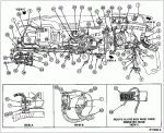
The Airbag Diagnostic Module (ADM) is light blue, wrapped in black foam, above the gas pedal
Air Bag Diagnostic Monitor Location diagram.
Item Part Number Description
1 — To Headlamp Switch
2 — To Fuse Box
3 14A282 Retainer Assembly
4 N606678-S39 *****
5 — Connector (Part of 12A581)
6 — Connector (Part of 14A504)
7 13A506 Locator, Position in Hole Provided
8 — To Park Signal Lamp Switch
9 — To Multi-Function Switch
10 — To Stoplight Switch
11 — Clip (Part of 14401)
12 — E4OD Pigtail (Part of 14401)
13 — To Ignition Switch and Steering Column Wiring
14 — To 14405
15 — To Starter Switch Clutch Interlock
16 — Take-Out to Shift on the Fly Switch and Electric Defrost Switch (Part of 14401)
17 — To Warning Buzzer Chime
18 — Remote Keyless Entry Programming Connector
19 15K602 Remote Keyless Entry Module
20 — Air Bag Module
21 14A163 Retainer Assembly
22 — To Trailer Brake Controller
23 14A099 Shield
24 — Vacuum Hose Clip (Part of Vacuum Harness)
25 — Ashtray Wiring (Part of 13726)
26 15A044 Cigar Lighter
27 — PSOM Test Circuit (Part of 14401)
28 — To Bowden Cable
29 18813 Radio Antenna
30 — Brake Anti-Lock Module Test Circuit (Part of 14401)
31 — To 14630
32 — To 14B095
33 — To 18A586
34 — To Right Courtesy Lamp Switch
35 — To Inertia Switch
36 14463 To Ground
37 — To Clearance Lamp F-Series Only for Continuation
38 — Wiper Control Module
39 2C018 Rear Brake Anti-Lock Module (F-150, F-250, F-350 Only)
40 — To Glove Box Lamp
41 — To Heater Mode Switch
42 — To A/C Illumination
43 — To A/C Blower Switch
44 — To Power Point
45 — To Radio
46 18B849 Premium Sound Amplifier
47 14B166 Shift on the Fly Switch
48 — To 14A262 Electric Defrost (Bronco Only)
49 14401 Wiring Assembly
50 — To Cluster (Plug A)
51 — To PSOM
52 — To Cluster (Plug B)
53 14B155 Cap
54 04320 Instrument Panel
55 9A050 Dual Fuel Tank Switch (F-Series Only)
56 14529 Rear Window Control Switch (Bronco Only)
57 — Demister Hose
58 — To Glove Box Lamp


