yo,
Since you have the (New? or rebuilt?) distr in there; some of the following
usually does not apply, esp the TFI Module troubleshooting along w/ the Hall Effect (also called da Profile Ignition Pick-up (PIP) Signal, or Stator, or RPM) since we all PRESUME these Hall Effects & Ign Modules are GOOD.. yeah, right. We've seen all kinds of crap coming in from that huge country that would like to blow us all up. And I would Never use any ignition module or hall effect other than Genuine Ford Motorcraft units.
btw, suggest that shop close it's doors or change it's name to.."Maybe It's This R-Us" because all they needed to do was open up the the Ford Electrical & Vacuum Troubleshooting Manual (EVTM) & Workshop Manual to do the troubleshooting; and they Should have done a self test for Diagnostic Trouble Codes (DTC);
DIY using my friend, BroncoJoe19's process; do the KOEO = Key On Engine Off portion first & after you get it running have engine @ Normal Operating Temperature before doing the KEY ON ENGINE RUNNING (KOER) portion
------------
Following is by Chilton;
Diagnosis & Testing-TFI-IV System
After performing any test which requires piercing a wire with a straight pin, remove the straight pin and seal the holes in the wire with silicone sealer.
The ignition coil must be diagnosed separately from the rest of the ignition system.
1.Primary resistance is measured between the two primary (low voltage) coil terminals, with the coil connector disconnected and the ignition switch off. Primary resistance should be 0.3-1.0 ohms.
IGNORE THIS > 2.On Dura Spark ignitions, the secondary resistance is measured between the BATT and high voltage (secondary) terminals of the ignition coil with the ignition OFF, and the wiring from the coil disconnected. Secondary resistance must be 8,000-11,500 ohms.
3.If resistance tests are okay, but the coil is still suspected, test the coil on a coil tester by following the test equipment manufacturer's instructions for a standard coil. If the reading differs from the original test, check for a defective wiring harness.
----
Supply Voltage
1.Attach the negative lead of a voltmeter to the distributor base.
2.Turn the ignition switch ON and connect the positive voltmeter lead to the positive (+) ignition coil terminal. Note the voltage reading then turn the ignition OFF. If the voltage reading is at least 90 percent of the battery voltage, yet the engine will still not run; first, check the ignition coil connector and terminals for corrosion, dirt, and/or damage; second, replace the ignition switch if the connectors and terminal are okay.
3.Connect any remaining wiring
--------------------------------------------------------------------------------
Primary Circuit Switching Test
1.Insert a small straight pin in the wire which runs from the coil negative (-) terminal to the TFI module, about 1 in. (25mm) from the module.
WARNING
The pin must not touch ground!
2.Connect a 12 VDC test lamp between the straight pin and an engine ground.
3.Crank the engine, noting the operation of the test lamp. If the test lamp flashes, proceed to the next test. If the test lamp lights but does not flash, proceed to the Wiring Harness test. If the test lamp does not light at all, proceed to the Primary Circuit Continuity test.
Primary Voltage
1.Attach the negative lead of a voltmeter to the distributor base.
2.Turn the ignition switch ON and connect the positive voltmeter lead to the negative (-) ignition coil terminal. Note the voltage reading and turn the ignition OFF. If the voltmeter reading is less than 90 percent of the available battery voltage, inspect the wiring between the ignition module and the negative (-) coil terminal, then proceed to the Ignition Coil Supply Voltage test.
-----------
Secondary Voltage
1.Disconnect the secondary (high voltage) coil wire from the distributor cap and install a spark tester between the coil wire and ground.
2.Crank the engine. A good, strong spark should be noted at the spark tester. If spark is noted, but the engine will not start, check the spark plugs, spark plug wiring, and fuel system. If there is no spark at the tester: Check the ignition coil secondary wire resistance; it should be no more than 5,000 ohms per foot. Inspect the ignition coil for damage and/or carbon tracking. With the distributor cap removed, verify that the distributor shaft turns with the engine; if it does not, repair the engine as required. If the fault was not found proceed to the Ignition Coil Primary Voltage test.
---------------
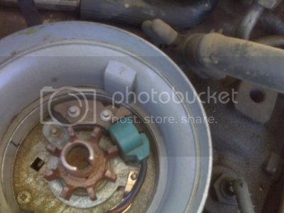
Next is the Hall Effect (also called da Profile Ignition Pick-up (PIP) Signal, or Stator, or RPM)
Here is a pic of it inside the distr. is by our pal here, YARDAPE

Its the blue gizmo there.
Stator Assembly And Module
1.Remove the distributor from the engine.
2.Remove the TFI module from the distributor.
3.Inspect the distributor terminals, ground ****** and stator wiring for damage. Repair as necessary.
4.Measure the resistance of the stator assembly, using an ohmmeter. If the ohmmeter reading is 800-975 ohms, the stator is okay, but the TFI module must be replaced. If the ohmmeter reading is less than 800 ohms or more than 975 ohms; the TFI module is okay, but the stator module must be replaced.
5.Repair as necessary and install the TFI module and the distributor
if you see any Chinese markings on it.. ya know da drill...
Wiring Harness
1.Disconnect the wiring harness connector from the TFI module; the connector tabs must be PUSHED to disengage the connector. Inspect the connector for damage, dirt, and corrosion.
2.Attach the negative lead of a voltmeter to the base of the distributor. Attach the other voltmeter lead to a small straight pin. With the ignition switch in the RUN position, insert the straight pin into the No. 1 terminal of the TFI module connector. Note the voltage reading. With the ignition switch in the RUN position, move the straight pin to the No. 2 connector terminal. Again, note the voltage reading. Move the straight pin to the No. 3 connector terminal, then turn the ignition switch to the START position. Note the voltage reading then turn the ignition OFF.
3.The voltage readings should all be at least 90 percent of the available battery voltage. If the readings are okay, proceed to the Stator Assembly and Module test. If any reading is less than 90 percent of the battery voltage, inspect the wiring, connectors, and/or ignition switch for defects. if the voltage is low only at the No. 1 terminal, proceed to the ignition coil primary voltage test.
------
\\

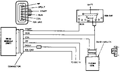
TFI schematic
........

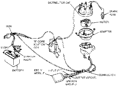
Exploded view of the TFI components
------------
The Thick Film Integrated (TFI-IV) ignition system uses a camshaft driven distributor with no centrifugal or vacuum advance. The distributor has a diecast base, incorporating a Hall effect stator assembly. The TFI-IV system module is mounted on the distributor base, it has 6 pins and uses an E-Core ignition coil, named after the shape of the laminations making up the core.
The TFI-IV module supplies voltage to the Profile Ignition Pick-up (PIP) sensor, which sends the crankshaft position information to the TFI-IV module. The TFI-IV module then sends this information to the EEC-IV module, which determines the spark timing and sends an electronic signal to the TFI-IV ignition module to turn off the coil and produce a spark to fire the spark plug.
The operation of the universal distributor is accomplished through the Hall effect stator assembly, causing the ignition coil to be switched off and on by the EEC-IV computer and TFI-IV modules. The vane switch is an encapsulated package consisting of a Hall sensor on one side and a permanent magnet on the other side.
A rotary vane cup, made of ferrous metal, is used to trigger the Hall effect switch. When the window of the vane cup is between the magnet and the Hall effect device, a magnetic flux field is completed from the magnet through the Hall effect device back to the magnet. As the vane passes through the opening, the flux lines are shunted through the vane and back to the magnet. A voltage is produced while the vane passes through the opening. When the vane clears the opening, the window causes the signal to go to 0 volts. The signal is then used by the EEC-IV system for crankshaft position sensing and the computation of the desired spark advance based on the engine demand and calibration. The voltage distribution is accomplished through a conventional rotor, cap and ignition wires.
-------------
Stator Assembly > Removal & Installation > Fuel Injected Engines > V8 Engines
1.Remove the distributor assembly from the engine; refer to the procedure in this section.
2.Remove the ignition rotor from the distributor shaft.
3.Mark the armature and distributor drive gear with a felt tip pen or equivalent, to note their orientation. While holding the distributor gear, remove the 2 armature retaining screws and remove the armature.
Do not hold the armature to loosen the screws.
4.Use a suitable punch to remove the roll pin from the distributor drive gear; discard the roll pin.
5.Position the distributor upside down in a suitable press. Using a press plate and suitable driver, press off the distributor drive gear.
6.Use a file and/or emery paper to remove any burrs or deposits from the distributor shaft, that would keep the shaft from sliding freely from the distributor housing. Remove the shaft assembly.
7.Remove the 2 stator assembly retaining screws.
8.Remove the octane rod and *****.
9.Remove the stator assembly.
10.Inspect the base bushing for wear or signs of excess heat concentration. If damage is evident, the entire distributor assembly must be replaced.
11.Inspect the base O-ring for cuts or damage and replace, as necessary.
12.Inspect the base for cracks and wear. Replace the entire distributor assembly if the base is damaged.
To install:
13.Position the stator assembly over the bushing and press down to seat.
14.Position the stator connector. The tab should fit in the notch on the base and the fastening eyelets should be aligned with the ***** holes. Be sure the wires are positioned out of the way of moving parts.
15.Install the 2 stator retaining screws and tighten to 15-35 inch lbs. (1.7-4.0 Nm). Install the octane rod.
16.Apply a thin coat of clean engine oil to the distributor shaft below the armature. Insert the shaft into the distributor base.
17.Place a 1/2 in. deep well socket over the distributor shaft, invert the assembly and place on the press plate.
18.Position the distributor drive gear on the end of the distributor shaft, aligning the marks on the armature and gear. Make sure the holes in the shaft and drive gear are aligned, so the roll pin can be installed.
19.Place a 5/8 in. deep well socket over the shaft and gear and press the gear until the holes are aligned.
If the shaft and gear holes do not align, the gear must be removed and repressed. Do not attempt to use a drift punch to align the holes.
20.Drive a new roll pin through the gear and shaft.
21.Install the armature and tighten the screws to 25-35 inch lbs. (2.8-4.0 Nm).
22.Check that the distributor shaft moves freely over full rotation. If the armature contacts the stator, the entire distributor must be replaced.
23.Make sure the back of the TFI-IV module and and the distributor mounting face are clean. Apply silicone dielectric compound to the back of the module, spreading thinly and evenly.
24.Turn the distributor base upside down, so the stator connector is in full view.
25.Install the ignition rotor onto the distributor shaft. Install the distributor as described in this section
---------------
Troubleshooting, Overview & Operation; "...Ford calls this electronic ignition the Thick Film Integrated-IV (TFI-IV) ignition system. The TFI module is also known as the Ignition Control Module (ICM) which reports engine position and rpm to the PCM. The PCM then determines the proper spark timing and advance, and returns a reference signal to tell the TFI module to switch the coil, thereby creating a spark. The PCM used on these vehicles is referred to by Ford as the Electronic Engine Control-IV (EEC-IV) module..." most is applicable to Broncos, read more Source: by therangerstation.com
Notice the difference in Ign Modules here as compared to the Chilton diagramsmiesk5 NOTE; use BLACK CCD Ignition Modules in
1994-1996 Broncos
See if you can find the part # on it; it's prob Not a Motorcraft unit I bet. I used to pull the module and place it on the intake manifold of a running engine and then test it; same for da hall effect.
Next up is the Troubleshooting Worksheet; miesk5 Note; this is the Grey Module Source: by therangerstation.com
-------------------------
Consider Ford Fuel Injection and Electronic Engine Control: How to Understand, Service and Modify, 1988-1993; & Ford Fuel Injection and Electronic Engine Control: How to Understand, Service, and Modify All Ford-Lincoln-Mercury Cars and Light Trucks, 1980 to 1987 by Charles Probst
avail @ BARNES & NOBLE, AMAZON, E BAY, ETC.


