yo sbujtas,
Ford changed name of the speedo/odometer in 1992 to Programmable Speedometer Odometer Module (PSOM)
BUT the Ford tech doc writers still refer to it as the speedometer... someone is not with da program!
Does ERROR 3 message alternate with normal odometer display?
Does Amber (Yellow) anti-lock lamp on instrument panel go out after starting and running?
Does the odometer display mileage increase with vehicle in motion?
the PSOM may be ok; could be a number of thAngs such as;
Connector loose or corroded @ back of PSOM; Inspect instrument cluster connectors and ensure proper fit. Inspect for loose or corroded terminals. Verify locking tabs are in place
Fuses; CHECK 8 & 18 (visual check, & test for continuity w/multi meter)
Fuse Block Diagram in a 92 Bronco & F Series; fuse H is a ****

this is from the Bronco Work Shop Manual;
SPEEDOMETER POINTER PROVEOUT
Press and hold the RESET button on the front of the speedometer (PSOM) -while turning the key to RUN.
Release the RESET button. The pointer would normally prove out, or sweep from the lower to upper pointer stop and back again. In this case, the pointer will "jump back" to where it should be in the sweep and continue to sweep normally when the pointer gets to within 180 degrees of the upper pointer stop (about 56 km/h [35 mph]).
Key off.
Does the pointer return to the normal position?
Yes = Speedometer normal.
No = REPLACE the instrument cluster or just da PSOM. VERIFY proper operation."
I used twine and zip ties to hold the instr cluster up and off the steering wheel and Head Light & TG window switches in relatively the same place
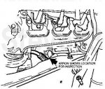
Speed Input Signal Test @ PSOM in 93-96 Bronco; "...NOTE: Only wiring harness end of connector is to be probed. * Connect Digital Volt-Ohmmeter to Pin 4 (speed in ) and Pin 5 (speed in -). * Does the voltage increase smoothly and continuously from 0 to approximately 3.5 volts as vehicle speed increases from 0 to 48 km/h (0 to 30 mph)?
OR: If available, a frequency counter may be connected to Pin 4 (Speed in ) and Pin 5 (Speed in -).
Does the displayed frequency of the signal increase smoothly and continuously from 0 to approximately 667 Hz at approximately 48 km/h (30 mph)?
OR: * If neither a voltmeter nor frequency counter is available, vehicle speed control may be used as a good indicator. If it works normally, then the speedometer module is at least receiving a speed input signal and the wiring and sensor & tone ring can be assumed to be good.
This is tuff to do; suggest using str8 pins to back probe the connector or a back probe kit

CHECK SPEEDOMETER SPEED OUTPUT SIGNAL; CAUTION: Before checking the continuity of any circuit, make sure there is no voltage present in the circuit prior to switching the test equipment to the resistance function to avoid damage to equipment. Refer to the test equipment user's manual for additional information. To determine if there is a short between the PSOM and the speed control module, the vehicle speed control may be used as a good indicator. If it works normally above 56 km/h (35 mph), this means that the speedometer module is at least receiving a speed input signal and the wiring and sensor can be assumed to be good. NOTE: Only wiring harness end of connector is to be probed. Use ohmmeter to check for opens in wiring between Pin 7 (speed out) and the affected module. Verify that the terminals in PSOM wiring connector are completely seated in the connector.
Is the circuit open?
Yes = SERVICE wiring between speedometer and affected module as required.
So let,s check for continuity from PSOM connector Pin #7 and cruise control using this Wiring Diagram in 96 (similar to 93-95)
Pin 3 in CC connector it is the GY/BK (Gray/Black wire)
I don't have the CC connector pin-out doagram so look for that Gray/Black wire
btw, was the Cruise Control recall work done yet?
Speedometer Inoperative in TSB 95-5-21 for 92-95 Bronco & F Series;
ISSUE: On some vehicles the HO2S wires in the 12A690 (subassembly of the 14B060 battery cable) harness may become chafed and the vehicle could exhibit any one of the following conditions:
ABS light on
Speedometer inoperative
Back-up lamps inoperative
Daytime running lamps inoperative
Trailer battery charge relay inoperative
MIL on, displaying Codes: 172, 173 or 41 for HO2S failure
Inadvertent PCM Self-Test

ACTION: Replace the damaged wire harness and HO2S sensor. Refer to the following procedure for service details.
SERVICE PROCEDURE:
1. Disconnect negative battery cable.
2. Disconnect the solenoid terminal and positive battery cable from the starter.
3. Pull the cable downward to inspect the 12A690 harness for chafing, pinholes, etc. If necessary, remove the convolute and tape from the 12A690 harness located next to the lower RH side engine mount.
4. If the 12A690 harness is damaged, replace the 14B060 assembly (F5TZ-14300-EA) and the HO2S sensor (F4UZ-9F472-A).
5. Inspect Fuse "E" and replace if necessary (D9ZZ-14526-D).
6. Clear all codes stored in memory.
7. Retest and verify the concern has been resolved.
PART NUMBER - PART NAME
D9ZZ-14526-D Fuse - 15 Amp
F5TZ-14300-EA Harness Assembly
F4UZ-9F472-A HO2S Sensor
For a PSOM (module);
YARD SEARCH on-line, I use;
http://www.mypartshop.com/
Select All Parts
year, etc, then FORD TRUCK
select Speedo Head/Cluster
buy PSOM alone; or entire cluster; if other gauges are out too.
get a money back or replacemt guarantee on it.
But most yards will sell only the entire instr cluster for about $50.00-$100.00
try to get one w/same mileage; you cann add mileage but can not subtract
then you can swap the PSOM (speedo/odometer) from your panel into the yard panel
The PSOM, lens, blackout ring, terminal clips, shifter plates, bulbs & holders are interchangeable between cases. '87-96 gauges are only held in by their terminal clips, except the speedo
92-96 PSOMs are held captive by the surrounding gauge faces
One thAng is, Gauges/cluster need to be stored in vertical or face-up positions. do Not lay any gauge or cluster face down; it will leak the dampening fluid. UPS still owes me $128.95 for Not following concise written shiiping instructions about placing the "Face-Up" labels on my cluster that I sent out to have it checked by a great shop (DNA Speedometers) (http://www.dnaspeedo...s.com/index.htm); Tampa, FL 33614
or
http://www.copartfinder.com
Has Vehicle Pics!
http://www.picknpull.com
http://www.car-parts.com/
I'll enter this now in case I lose Cable connection again
Cluster Removal in 92-93 & 94-96 F Series, similar to Bronco Source: by tomtoc
Cluster Removal in a 95; part of Chris's Halo Reverse Glow Installation; miesk5 Note First, start Bronco & Shift to L or 1; turn key off;
& Steve83 wrote, I always unhook the cable, then spin the wheel. You can't really get to the indicator end to unhook it - I do it at the shifter (wheel) end. There's nothing inherently wrong with removing the wheel assy. But when you're trying to pull the cluster, it's easier to feed the bare cable end back around the column & thru the wiring harness. If the cable sheath is white, it's probably about to break no matter how careful you are. If it's black with mesh reinforcement, you almost can't break it; "...the adjusting wheel is for 92-up columns
Source: by dadtodc (Chris B) at
https://plus.google.com/photos/117624469589686867733/albums/5573384105450485937?authkey=CK2IyfWByNj23wE&banner=pwa&gpsrc=pwrd1#photos/117624469589686867733/albums/5573384105450485937