Yo Jeff,
Welcome!
You addressed the fuel managers at cold start & normal operation,
IAC, TPS and ECT sensors, however, testing those sensors may be needed.
For no,w let's look another perpetrator(s).
Have you checked for Diagnostic Trouble Codes《on a cold engine and when at normal operating temperature?
Here are test methods other thanwith a scan tool @
https://www.therangerstation.com/tech_library/OBD_I.shtml
□
Vacuum Leak in a Cold Engine:
One way to do a quick check is to grab a vacuum gauge. Some parts stores will loan you a gauge with refundable deposit.
The vacuum gauge should read between 15 and 22 in-Hg depending upon the engine condition and the altitude at which the test is performed. SUBTRACT ONE INCH FROM THE SPECIFIED READING FOR EVERY 1,000 FEET OF ELEVATION ABOVE SEA LEVEL.
The reading should be quite steady. .
When engine is rapidly accelerated (dotted needle), needle will drop to a low (not to zero) reading. When throttle is suddenly released, the needle will snap back up to a higher than normal figure.
When vacuum leaks are indicated, search out and correct the condition.
Excess air leaking into the system will upset the fuel mixture and cause conditions such as rough idle, missing on acceleration, or burned valves. If the leak exists in an accessory unit, such as the power brake, the unit will not function correctly. Or Air Conditioning when in MAX mode may switch to Defrost.
□
A friend had same issue, he. noticed a crack in the Y-pipe adjacent to the O2 sensor. When the exhaust warmed up it then sealed the minor air leak. So the sensors vacuum hoses could have an issue when colf
•○¤
Oxygen Sensor Testing, Bronco & Ford; "...three wire O2 sensors; two gray wires and one black. The black should read ground. One gray wire should read 12V with the ignition on, and the other gray wire is the one we are after. Probe this wire with the engine warm, and running with a voltmeter’s (+) probe, and ground the negative probe. While the vehicle is running, the reading should be approximately 0.5V. A reading below this indicates a lean air fuel mixture; a reading above this indicates a rich mixture. If no reading is present, and all connections are good, the sensor is probably in need of replacement.." by Ford
⊙●⊙
Next Up to Bat is the Diode Leakage Test; "...To check alternator diode leakage, connect the multimeter in series with the alternator output terminal when the car is not running. Leakage current should be a couple of milliamps at most; more often, it will be on the order of 0.5 milliamps. Use care when disconnecting the alternator output wire; make sure the battery is disconnected first..." by Fluke
A long shot on an Alernator Bad Bad Waveforn; @
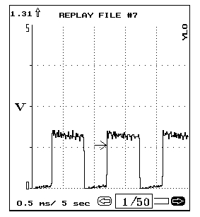 Bad IAC Waveform
This waveform was captured using the lab scope. This is a good example of how an alternator with a bad diode can affect other signals that the ECM looks at. In this case it is an
IAC motor.
When viewing waveforms that have a lot of hash always look at the alternator diode pattern as a possible cause.
&
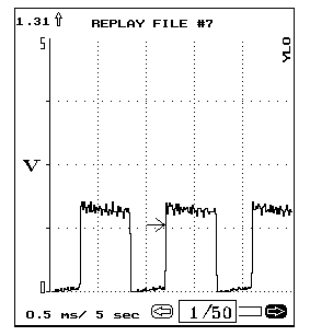
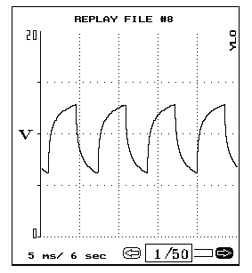
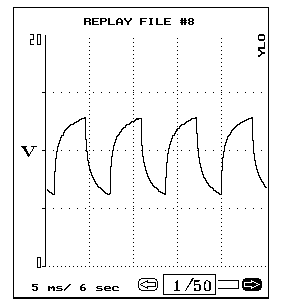 Ford Idle Air Control
This is a typically good ford idle air control (IAC) motor waveform. The Ford IAC waveform has its own unique "sawtooth" signature. The IAC valve is being pulsed and the duty cycle determines the volume of air through the valve.
A 100% duty cycle is fully open and a 0% duty cycle is fully closed. When checking this solenoid look for dropouts or spikes in the waveform that could indicate a problem
□■□
Also fyi, Loose or Weak Contact at Generator Harness Connector TSB 96-21-4 for 86-93 Bronco & F Series, etc.includes your BII
ISSUE: When a generator fails, there are a few failure modes that may cause heat to be produced at the wiring harness-to-generator connector. This excess heat may damage the female terminals on the wiring harness, resulting in increased resistance. The increased resistance produces more heat. When the generator is replaced, the resistance produced by a damaged connector may damage the new generator and could result in a repeat repair, including installation of another generator. High resistance (caused by a damaged connector) will not go away until the damaged connector is replaced.
ACTION: Visually inspect the harness-to-generator connector for damage (heat, corrosion, distortion and cracking) before installing a new generator. Install the Generator Wiring Harness Connector Kit (E5AZ-14305-AA) if the harness-to-generator connector is damaged.
The Generator Wiring Harness Connector Kit (E5AZ-14305-AA) contains the following:
One (1) Red Wire Butt Connector
Two (2) Yellow Wire Butt Connectors
One (1) Wire Connector Assembly
One (1) Instruction Sheet (I.S. 6849)
PART NUMBER PART NAME
E5AZ-14305-AA Generator Wiring Harness Connector Kit
◇⊙◇
Al

