ledzilla
Active member
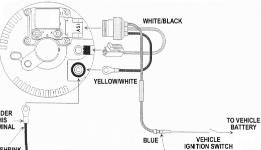
Ok, so I took a look at the wiring installation for the alternator, and I think I'm on the right track. Now, the wiring for the alternator's connectors is a different color because it was a different brand of alternator and conversion pigtails installed, but the connections look the same. That 1.3V wire is supposed to be switched 12V connected to the "blue" wire in the attached diagram. So, where ever that factory green wire runs, yeah, there has to be some damage to it where it occasionally loses some part of the circuit, either through internal damage to the wire or a bad connection at the other end. So if I either repair that wire or for now just run a separate wire providing switched 12V, in theory that should fix the problem.
I have also seen a few things that say the voltage sensing wire shouldn't be connected to the alternator's B terminal, but instead at the point where everything connects for power (along with a 10A inline fuse). In my current setup I'm not sure that will really make a difference since everything sources from the 350A distribution block I mounted to the wheel well. Those connections all feel pretty secure still.
I have also seen a few things that say the voltage sensing wire shouldn't be connected to the alternator's B terminal, but instead at the point where everything connects for power (along with a 10A inline fuse). In my current setup I'm not sure that will really make a difference since everything sources from the 350A distribution block I mounted to the wheel well. Those connections all feel pretty secure still.


