95 Bronco with 351

Disclaimer: Links on this page pointing to Amazon, eBay and other sites may include affiliate code. If you click them and make a purchase, we may earn a small commission.

OP
OP
B
Joined
Jan 21, 2011
Messages
13
Reaction score
0
Location
Mississippi
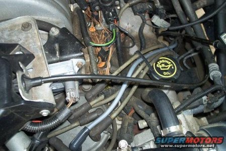
ok i believe this is a picture of what i am supposed to be looking for is the aluminum rectangle with the plug sticking out of it. it is mounted right beside the EGR valve on a bracket correct?

egr.jpg

if that is where it is supposed to be, there is nothing mounted to the bracket but i have a cylinder with two wires going into the top of it. is this the same thing or is mine missing? and from looking at the diagrams there should be something running from the egr valve to this DFPE i cant find anything coming from the egr valve except the main vaccuum line. UUUHHHHHHH im going crazy chasing this gost problem that i have no idea as what im looking for.


miesk5

96 Bronco 5.0
Staff member
Moderator
Joined
Oct 18, 2005
Messages
9,071
Reaction score
1,019
Location
Floating in the Pacific
ok i believe this is a picture of what i am supposed to be looking for is the aluminum rectangle with the plug sticking out of it. it is mounted right beside the EGR valve on a bracket correct?

egr.jpg

if that is where it is supposed to be, there is nothing mounted to the bracket but i have a cylinder with two wires going into the top of it. is this the same thing or is mine missing? and from looking at the diagrams there should be something running from the egr valve to this DFPE i cant find anything coming from the egr valve except the main vaccuum line. UUUHHHHHHH im going crazy chasing this gost problem that i have no idea as what im looking for.

yo, that is where it is supposed to Mount;

this is another DPFE Sensor Location pic in my 96 5.0; Older Aluminum Rectangular Version, driver's side above distributor in a 96 5.0; - MIESK5 NOTE: only 95 5.8L California models & all 96 have the DPFE Sensor instead of EGR Valve Position Sensor (EVP)

Source: by miesk5 at SuperMotors.net

dpfesilverboxwconnector.jpg

here is a close-up pic

140.jpg

 
Last edited by a moderator:
OP
OP
B
Joined
Jan 21, 2011
Messages
13
Reaction score
0
Location
Mississippi
ok here is a picture of what i have.... i have searched this truck over and it is NOT here. I have looked above Dist. as well as you show on your 5.0 not there either. please take a look at this and let me know what you think. Also Today in messing with the truck i am now having problems starting it...... It starts but will not always stay running i have to keep re-starting it and eventually it will stay running. dont know if this changing problem may help in the diagnosis of my Agravation Problem.

Bronco EGR valve.jpg


miesk5

96 Bronco 5.0
Staff member
Moderator
Joined
Oct 18, 2005
Messages
9,071
Reaction score
1,019
Location
Floating in the Pacific
yo,

ok

you have the non cal EGR Valve Position Sensor (EVP)

sorry about that but the code you posted always has (until now) indicated it is a 95 5.8 calif smogged Bronco

so

pic in a 5.8; Miesk5 Note EVP is light gray & attached to the top of the EGR Valve

Source: by Travis L

egr-connector.jpg

egrtubesv8.jpg

Overview & Parts Break-Out Diagram for 5.0 & 5.8; SEE & READ MUCH MORE

Source: by Steve83 (Steve, That dirty old truck) at http://www.supermotors.net/registry/media/826382

Testing & Operation; "...The EGR Valve Position (EVP) sensor monitors the position of the EGR valve pintle. The EVP sensor converts the mechanical movement of the pintle into an electrical voltage signal which is relayed to the PCM. The EVP sensor is a linear potentiometer in which resistance varies with the EGR valve pintle movement.Voltage is fed to the EVP by the signal return circuit. As the EGR is opened the EVP directs more voltage to the EEC and less down the voltage reference circuit. The EVP sensor provides the PCM with information on EGR flow and EGR system failures. The EVP should read between 0.24 and 0.67volts at idle with a closed EGR valve..." read more

Source: by Ryan M (Fireguy50) at http://fordfuelinjection.com/index.php?p=35

Testing; "...Using the Haynes manual's procedures, you should be able to back-probe the EVP line and ascertain whether the EVP voltage is correct. It should be below 0.67V @ zero vacuum on the EGR, slowly increasing with applied vacuum from a hand pump. DO NOT apply more than 10 in-Hg to the valve..."

Source: by SigEpBlue (Steve)


miesk5

96 Bronco 5.0
Staff member
Moderator
Joined
Oct 18, 2005
Messages
9,071
Reaction score
1,019
Location
Floating in the Pacific
Continuous Memory DTC 327 indicates the EGR valve was closed further than normal or EVP sensor or circuit has failed with an intermittent low voltage sometime during vehicle operation.


miesk5

96 Bronco 5.0
Staff member
Moderator
Joined
Oct 18, 2005
Messages
9,071
Reaction score
1,019
Location
Floating in the Pacific
MF!

You won't be able to do all of this because of the freakin' break-out box ***** so do the shake n bake on the EVP sensor harness, etc.

Continuous Memory DTC 337 indicates the EVP signal to the Powertrain Control Module (PCM) was above the maximum Self-Test limit sometime during vehicle operation.

Possible causes:

-- Poor continuity in EVP harness or connectors.

-- Intermittent open or short in EVP sensor or harness.

-- Damaged EVP sensor.

l Disconnect Powertrain Control Module (PCM). Inspect for damaged or pushed out pins, corrosion, loose wires, etc. Service as necessary.

l Install breakout box, reconnect PCM.

l Connect DVOM between Test Pin 27 and Test Pin 46 at the breakout box.

l Key on, engine off.

l Lightly tap on EVP sensor and wiggle harness connector to simulate road shock.

NOTE:

EVP voltage with EGR valve closed is normally between .24 and .67 volt and steady. A sudden change in voltage indicates a fault.

l Is a fault indicated?

Yes

REMOVE and INSPECT EVP sensor connector. If OK, REPLACE EVP sensor. CLEAR Continuous Memory (REFER to Quick Test Appendix, «Section 5A»). RERUN «Quick Test».

No

LEAVE DVOM connected, RECONNECT PCM and GO to «DN91».

DN91 CHECK EEC-IV VEHICLE HARNESS FOR INTERMITTENT OPENS OR SHORTS

l Key on, engine off.

l DVOM connected between Test Pin 27 and Test Pin 46 at breakout box.

-- Grasp the vehicle harness closest to the EVP sensor connector. Shake and bend a small section of the EEC-IV harness while working toward the dash panel. Also wiggle, shake and bend the EEC-IV harness from the dash panel to the PCM.

l Is a fault indicated?

Yes

ISOLATE fault and SERVICE as necessary. CLEAR Continuous Memory (REFER to Quick Test Appendix, «Section 5A»). RERUN «Quick Test».

No

LEAVE DVOM connected and GO to «DN92».

DN92 CHECK VOLTAGE WHILE EXERCISING EGR VALVE

l Disconnect vacuum hose at EGR valve and connect a vacuum pump.

l Key on, engine off.

l Measure voltage between Test Pin 27 and Test Pin 46 at the breakout box while performing the following:

-- Slowly apply 5-10 in-Hg (17-34 kPa) of vacuum to EGR valve, then slowly bleed vacuum.

l Does the voltage increase and decrease steadily from no more than 4.81 volts to no less than .24 volt?

Yes

Unable to duplicate and/or identify fault at this time. For further diagnosis using the EEC-IV monitor box or Scan Tool, REFER to «Section 7A».

No

REPLACE EVP sensor. REMOVE breakout box. RECONNECT all components. RERUN «Quick Test».


miesk5

96 Bronco 5.0
Staff member
Moderator
Joined
Oct 18, 2005
Messages
9,071
Reaction score
1,019
Location
Floating in the Pacific
yo,

Sorry, ISP kept turning off.

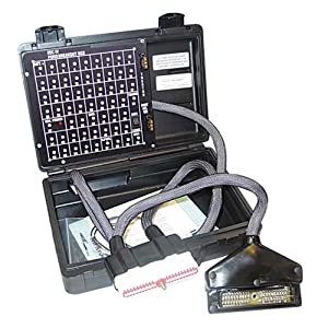
the breakout box allows testing of all engine input signals such as the EVP sensor and all computer generated output signals. It fits between engine computer (EEC) and connector so that circuits can be tested for voltage or resistance. Unfortunately, they are costly and most of us use wiring diagrams and voltage or resistance specs to test manually w/a digital multimeter.

51xmrbTTjKL._SL500_AA300_.jpg


miesk5

96 Bronco 5.0
Staff member
Moderator
Joined
Oct 18, 2005
Messages
9,071
Reaction score
1,019
Location
Floating in the Pacific
So 327 was solved when "...found that the plug on top of the EGR valve was loose, i plugged it back up and re-ran the KOER test now i have the following Codes..."

This jumping between page 1 and 2 is killing my eyesight. sorry, but I have some floaters that drive me nuts.. I thought I saw Code 337.. but that stuff was good for 327..so

Try and read thru the TFI diagnostic Links for DTC 213 or shake that SPOUT harness and re test for Codes..since a previous owner or shop seems to have replaced it w/ a Spout jumper that looks like new.

Here is the Ford pin-point tests whci invlove disco the harness @ computer (called PCM here)]

http://ww2.justanswer.com/uploads/n9320h/2009-12-06_153133_pa1.gif


miesk5

96 Bronco 5.0
Staff member
Moderator
Joined
Oct 18, 2005
Messages
9,071
Reaction score
1,019
Location
Floating in the Pacific
n a previous reply, you mentioned that Link in my site by Brian...

Here it is by Ford..it deals w/DTC 211 but it mentions where Shorts to ground caould occur @ shielding...

TSB 95-15-11 Hesitation, Stumble, Stall, Miss, No Start, No Spark

ISSUE: '93-95 light truck vehicles with 4.9L, 5.0L, 5.8L, or 7.5L gas engines may exhibit various driveability symptoms, such as no start, no spark, hesitation/stumble/stall/miss and/or Diagnostic Trouble Code (DTC) 211. The symptoms may occur during any drive mode or at idle. These concerns may be caused by the shielding drain wire (Circuit 48.) cutting through the insulation of, and shorting to, the Profile Ignition Pickup (PIP) wire (Circuit 395) or the spark output (SPOUT) wire (Circuit 929) near the Powertrain Control Module (PCM) 60-pin connector. A protruding wire from Splice 145 may also cause the same concern as the wire strand shorts to the PIP, SPOUT, or the foil wrap surrounding the drain wire.

ACTION: Inspect PIP - Circuit 395 (GY/O), Ignition Ground (IGN GND) - Circuit 259 (O/R), and SPOUT - Circuit 929 (PK) for possible cut insulation from Circuit 48. Also, inspect Splice 145 - Circuit 395 (GY/O) for stray wire strands. If wire insulation is cut, exposing copper wire, repair cut insulation with 3M Mastic Tape. Refer to the following procedure for service details.

SERVICE PROCEDURE

1. Disconnect battery ground cable.

2. If vehicle has the speed control option, remove the speed control servo bracket and position it out of the way for improved access.

3. Disconnect the connector at the Ignition Control Module (ICM - formerly TFI).

4. Unbolt the 60-pin connector from the PCM and pull the wiring up to work on.

5. Remove the 1" (25.4mm) diameter convoluted tubing from the wiring assembly. The date code tag will remain taped to the convoluted tubing.

6. Remove/cut the tape of the wiring assembly. Work toward the the ICM connector (pull back convoluted tubing as needed).

7. Unravel aluminum foil tape and electrical drain wire (Circuit 48.) from main bundle, exposing the junction or "Y" splice between the ICM tapeout and the PCM tapeout. Be careful with the foil wrap because it will be reused.

NOTE: THE FOIL WRAP LENGTH WILL BE ABOUT 5" (127mm) BEYOND THE "Y" BRANCH. THE END WILL BE TOWARD THE ICM CONNECTOR.

8. After the foil wrap is removed, look for the three (3) "grouped" wires in question at the "Y" splice. The three (3) wires are: PIP - Circuit 395 (GY/O), IGN GND - Circuit 259 (O/R), and SPOUT - Circuit 929 (PK).

9. Locate the (bare) electrical drain wire. Wire end is toward the ICM connector, again, about 5" (127mm) from the "Y" splice. Unravel wire from the top (ICM) end and down to the area where the bare wire makes contact with the three (3) wires mentioned above.

10. Inspect for any damage to the insulation of the three (3) wires in question. If wire insulation is cut, exposing copper wire, repair cut insulation with 3M Electrical Moisture Sealant-Mastic Tape (3M Part No. 054007-06147).

11. Inspect Splice 145 - Circuit 395 (GY/O) for stray wire strands (Figure 3). If stray wire is found, apply pressure on the wire with pliers to bend the wire down and wrap the splice with three (3) layers of flame retardant vinyl tape, or equivalent, to ensure the wire does not make contact with other wires or the foil wrap.

12. Carefully rewrap the bare electrical drain wire and foil. Work backward, toward the ICM connector end. Tape end of foil wrap to secure.

13. Retape worked area securely (between PCM and ICM connectors) with flame retardant vinyl tape, or equivalent.

14. Reinstall all convoluted tubing and tape ends of tubing to the tubing with flame retardant vinyl tape, or equivalent.

15. Reinstall PCM connector to the PCM.

16. Reinstall the ICM connector.

17. Reinstall the speed control servo bracket (two bolts) if applicable, and tighten bolts to 15-18 N-m (11-13 lb-ft).

18. Reconnect battery ground cable.

tsb951511pipstall.jpg

by Ford via Steve83

I hate touching these old connectors, esp @ PCM!

Maybe stop by local Ford dealership and question Service Manager about this Short; if he or she jumps on the problem and seems to know where to look it will save you a lot of grief.

and here is da ign diagram for a F 150 but similar

http://fordfuelinjection.com/files/bronco_1995_21-1.gif by Ryan M

SPOUT is shown in upper left

check both Pink wires from SPOUT for short; one wire goes to Ignition Module (pic below)

other goes thru shielding (poss short to ground location) to PCM pin 36

Ignition Control Module (ICM) Location pics (near driver's side hood hinge) & info in a 96 5.8; "...Spout connector wires go into ignition module wiring connector..."

Source: by DNBELOWBRONCO (Kevin, Labor of Love) at SuperMotors.net

spout-connector-location-96-5.8-002.jpg

Ignition Control Module (ICM) pic Source: by buzzbronco

aluminum-sensor-1.jpg

This diagram may help for other stuff too:

Ignition Control Module (ICM) Location (near driver's side hood hinge)in Engine Bay Diagram in 92-96 Source: by Ford via miesk5 at broncolinks.com/gallery

 
OP
OP
B
Joined
Jan 21, 2011
Messages
13
Reaction score
0
Location
Mississippi
sorry for the delay of response after messing with all kinds of stuff I have fixed the 213 code now I am getting a 536 & 632 can you please tell me what these are referring to. Also can you please send me a link of where I can find a list of codes. P.s. This is the KOER test my KOEO Test gave me a 111 which I believe is a pass. Thank you for your help.


miesk5

96 Bronco 5.0
Staff member
Moderator
Joined
Oct 18, 2005
Messages
9,071
Reaction score
1,019
Location
Floating in the Pacific
yo! Good!

What did you do to eliminate that 213?

And you ARE IN LUCK on the New Codes

DTC 536 - Brake On/Off circuit failure / switch not actuated during KOER test or shorted to ground

Source: by miesk5

DTC 632 - OD cancel switch not changing state. "...During the KOER test, AFTER the initial recognition code is generated, the brake pedal must be applied, the OD switch must be turned off and then back on and finally the "goose" test must be performed. This code is generated when the person performing the KOER test fails to deactivate and reactivate the OD cancel switch at the end of the shift lever. It does NOT indicate a problem unless the switch WAS INDEED deactivated and reactivated and the code still came up. (Computer needs to know if the tranny is in OD or not

Both in KOER portion of the self test the brake pedal must be depressed and the OD off/on sw at end of shifter stalk must be turned on and off;

Here is a list of DTCs 3 Digits Source: by Ryan M (Fireguy50) at fordfuelinjection.com

And I have a bunch incl that Link in site; under

EEC-IV; SELF TEST & Diagnostic Trouble Code (DTC), Overview, etc

or use my Search feature there; just type in the number...

no "DTC" needed, just da number

=============================

for da SELF TEST in future or now;

KOEO & KOER TESTS:

The engine temperature must be greater than 50°F (10°C) to pass the KOEO Self-Test and greater than 180°F (82°C) to pass the KOER Self-Test.

Run it around to heat the engine up and shift thru all gears incl Reverse. Then turn off all accessories/lights, etc.

Make sure A/C is off and transmission is in Park (automatic) or in Neutral for a Manual & release clutch.

Do Key On Engine Off (KOEO) portion first.

Engine ID codes are issued at the beginning of the KOER Test and are one-digit numbers represented by the number of pulses sent out.

During KOER; For gasoline engines, the engine ID code is equal to one-half the number of engine cylinders (i.e. 4 pulses = 8 cylinders).

The Dynamic Response code is a single pulse that occurs 6-20 seconds after the engine identification code. When/if the Dynamic Response code occurs, perform a brief Wide-Open Throttle (WOT). The dynamic response check is used on some applications to verify operation of the TP, MAF, MAP & KS sensors.

On vehicles equipped with the Power Steering Pressure (PSP) switch, within 1 to 2 seconds after the ID code, the steering wheel must be turned at least one-half turn and released. The PSP Switch signals the EEC Module when power steering pressure exceeds 350 psi ±50. The engine then increases idle speed to compensate for the additional load. It appears the PSP switch was deleted from the 94 model year. PSP Switch is screwed into the high pressure port of the PS pump(5.0L Only).

On vehicles equipped with Brake On/Off (BOO) input (such as E4OD), the brake pedal MUST be depressed and released AFTER the ID Code has been displayed. This tests the ability of the EEC system to detect a change of state in the Brake Lamp Switch.

On vehicles equipped with Transmission Control Switch (TCS) such as da E4OD, the switch must be cycled after the ID code has been displayed. This tests the ability of the EEC system to detect a change of state in the TCS. TCS = Transmission Control Indicator Light (TCIL) on E4OD it is also ref to as the OD on/off LED/Switch @ end of tranny gear stalk.

 
OP
OP
B
Joined
Jan 21, 2011
Messages
13
Reaction score
0
Location
Mississippi
to fix the 213 I had unplugged the ICM while the truck was running it killed the truck I plugged it back in and then retested and it was gone. But I need to know where the relay for the fuel pump is located. And how do I test one of those relays.


miesk5

96 Bronco 5.0
Staff member
Moderator
Joined
Oct 18, 2005
Messages
9,071
Reaction score
1,019
Location
Floating in the Pacific
yo,

FP Relay is in Power Distribution Box located under the hood on the drivers side fenderwell, on driver's side of the air cleaner housing

http://www.froggmann.com/Images/ABSCut1.jpg

pic by Froggmann (Ken P) at froggmann.com

http://broncozone.com/index.php?app=core&module=attach&section=attach&attach_rel_module=post&attach_id=10312

Diagram in a 95

Source: by our friend, Seabronc (Rosie, Fred W) at Ford Bronco Zone Forums

If your Horn works, then swap the Horn Relay w/FP relay

also same for PCM Power relay which feeds power to EEC and then on to the FP Relay.

Buy Bosch relays..

For the electrical test, this was presented here by another friend, BroncoJoe;

Testing, Ford (Bosch Type); "...Fuel pump relay switches, and other relays are similar to the starter solinoid, in that they make a high amperage connection through a switched low amperage connection. There are two smaller connections, and two larger connections. TO test it, apply 12v to one of the smaller connections, and ground the other smaller connection. (I used to small aligator clipped jumper wries separated by a small piece of cardboard to keep them from shorting against each other.) You should hear it click. Then check for continuity between the two larger connections.Now remove the power from the smaller connections and recheck continuity between the larger connections.With power, one should have continuity, without power it should be an open circuit (no continuity)..."

Source: by Poppy at fordforumsonline.com


Members online

No members online now.

Latest posts

Forum statistics

Threads
22,521
Messages
135,985
Members
25,126
Latest member
Lana Kane
Top