ShadetreeSeattle
Member
- Joined
- Feb 21, 2017
- Messages
- 42
- Reaction score
- 18
Alrighty, today we will be doing the 2nd gen to 3rd gen alternator switcheroo on a 1988 Bronco1 with the 4.9L 300CI inline 6.
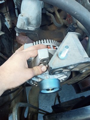
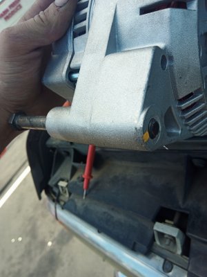
the install for the 4.9L was not that difficult at all, the factory alternator bracket already had mounting provisions for the larger alternator. I have to break up this post into parts because of the 10K character limit on here.
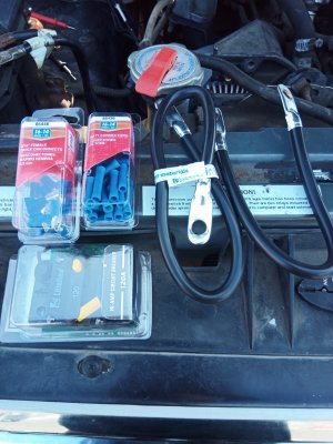
Part 1: Parts/tools needed: (parts all sourced from o'reilly auto)
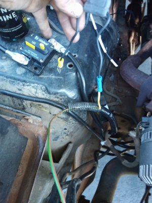
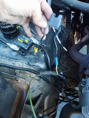
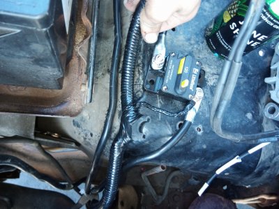
1x 125A circuit breaker (on shelf in electrical isle)
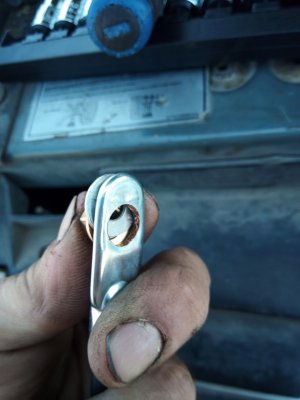
2x 24" 4AWG wires with crimp end ring terminals on each end
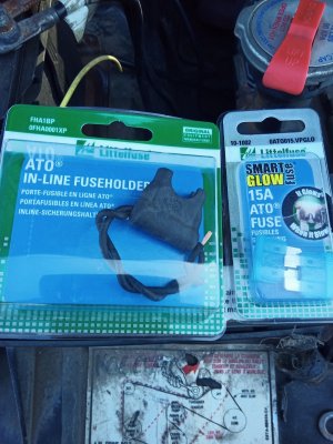
1x 15A blade fuse holder
1x 15A fuse
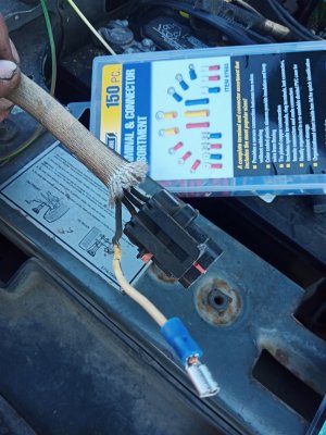
1x small pack of 3/16 female quick disconnect terminals or a donor 3G alternator wire harness
1x small pack blue crimp butt splice terminals
1x small pack assorted yellow crimp ring terminals
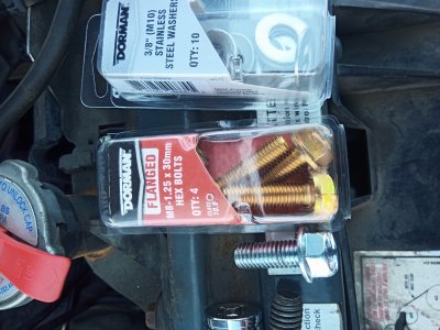
1x m8 x1.25 by 30MM bolt
1x small pack of washers, 3/16 ID or whatever you have laying around.
Zip ties
Electrical tape (get the nice scotch stuff, it's actually somewhat tolerant of under hood temperatures)
Socket set, imperial and metric
A decent crimp tool, one which has the non-insulated tooth. (the ones which just squish the terminal flat are useless)
Okay, PART 2. 2G removal and prep for 3G.
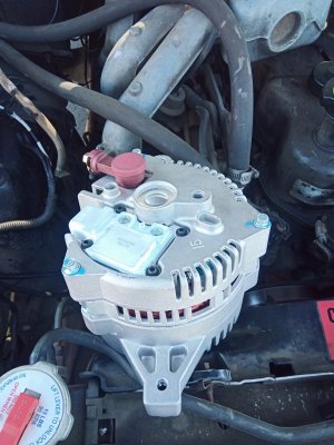
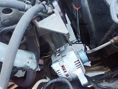
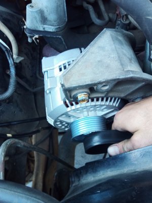
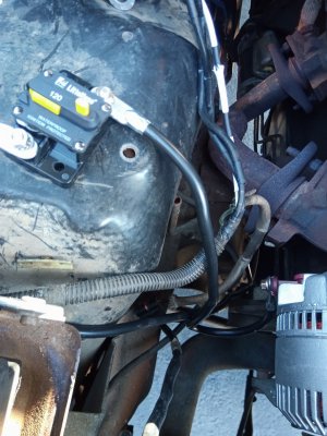
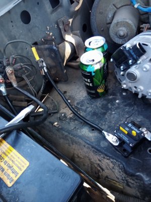
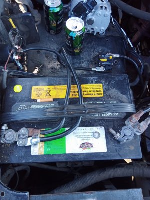
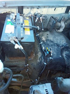
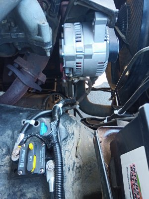
Here's the final install BTW, what I ended up with.
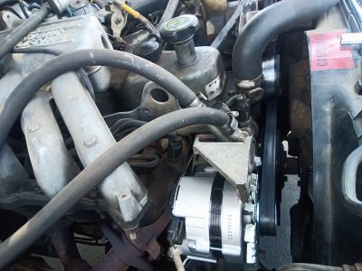
Here's the old, Existing setup with the 2G alternator below:
Step1, disconnect battery, remove the old alternator, remove belt. I was a daredevil and left my battery connected because the truck runs like #%$@ for a while if the computer looses it's keep-alive memory. I don't recommend keeping the battery connected. I was being stubborn. Don't be dumb like me. XD
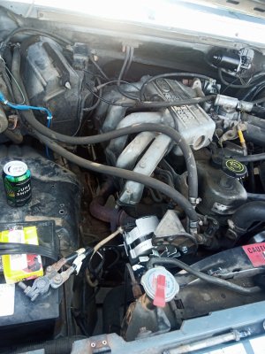
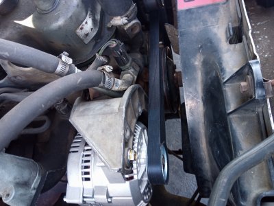
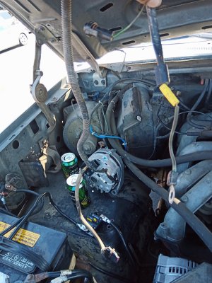
One beer in! one bolt out! haha. Notice in below photo how I have removed the air pump previously, if your air pump system is defunct/non functioning anyways, perhaps a good time to pull it out and re-route the belts since you will, with this 3G alternator upgrade need to install a custom length belt anyways. Always consider if you have emissions laws which will not allow your vehicle to pass without an air injection pump and also, all the other things one needs to do to remove the entire air injection (smog pump) system.
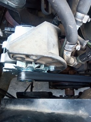
Another pic of my belt routing without air pump or a/c
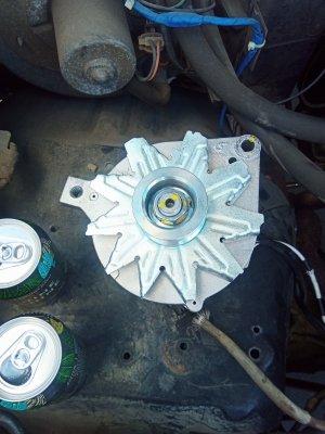
Here's the original 2G alternator, with the 2 and 6 o'clock mounting ears. on the engine's alternator mounting bracket we will no longer utilize either of the mounting positions used by the 2G alternator.
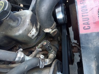
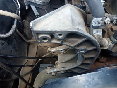
Alternator removed, observe below, the original 2 and 6 o'clock mounting holes (more to the right) and the 12 and 6 o'clock mounting positions to the left we will now be utilizing. Ignore the top most threaded hole on the mounting bracket and the very bottom most swivel mount which was originally for the air pump. neither will be utilized.
Below, observe the original mounting ear configuration between the old 2G alternator and the new 3G alternator. We will not be using either of the original mounting holes from the 2G alternator as they are spaced narrower from eachother and in a different position from our 3G alternator.
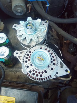
Below, observe the backsides of the 2G (upper in picture) and 3G (lower in picture) alternators. With lower mounting ear to the right we see that the electrical connections are facing the wrong direction from the original, 2G alternator. To fix this we remove the 3 bolts from the 3G's casing and carefully rotate the rear half of the alternator case CCW to the next position it can bolt back together. This will aim the voltage regulator and V+ connectors downward and toward the passenger side instead of in toward the engine block which will not work.
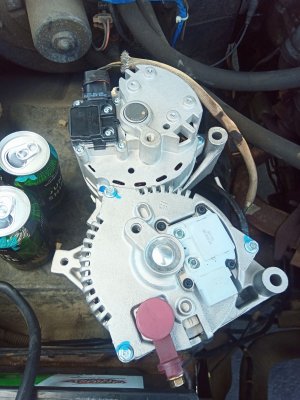
Again observe how the 3G alternator's connections will face toward the engine block instead of away and down.
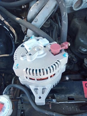
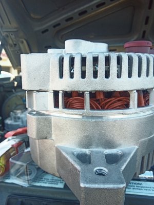
Bolts out, gently pry the casing enough to unseat it so it can be rotated. the casing is in three pieces, the front half is bottom in below image, mid section is middle in image, top section is the top (rear) of the alternator. the front (lower in image) and mid are to be separated slightly and rotated CCW to the next point which the bolt holes line up. do not try to rotate the top (rear) and mid sections as they are electrically connected together.
the install for the 4.9L was not that difficult at all, the factory alternator bracket already had mounting provisions for the larger alternator. I have to break up this post into parts because of the 10K character limit on here.
Part 1: Parts/tools needed: (parts all sourced from o'reilly auto)
1x 125A circuit breaker (on shelf in electrical isle)
2x 24" 4AWG wires with crimp end ring terminals on each end
1x 15A blade fuse holder
1x 15A fuse
1x small pack of 3/16 female quick disconnect terminals or a donor 3G alternator wire harness
1x small pack blue crimp butt splice terminals
1x small pack assorted yellow crimp ring terminals
1x m8 x1.25 by 30MM bolt
1x small pack of washers, 3/16 ID or whatever you have laying around.
Zip ties
Electrical tape (get the nice scotch stuff, it's actually somewhat tolerant of under hood temperatures)
Socket set, imperial and metric
A decent crimp tool, one which has the non-insulated tooth. (the ones which just squish the terminal flat are useless)
Okay, PART 2. 2G removal and prep for 3G.
Here's the final install BTW, what I ended up with.

Here's the old, Existing setup with the 2G alternator below:

Step1, disconnect battery, remove the old alternator, remove belt. I was a daredevil and left my battery connected because the truck runs like #%$@ for a while if the computer looses it's keep-alive memory. I don't recommend keeping the battery connected. I was being stubborn. Don't be dumb like me. XD

One beer in! one bolt out! haha. Notice in below photo how I have removed the air pump previously, if your air pump system is defunct/non functioning anyways, perhaps a good time to pull it out and re-route the belts since you will, with this 3G alternator upgrade need to install a custom length belt anyways. Always consider if you have emissions laws which will not allow your vehicle to pass without an air injection pump and also, all the other things one needs to do to remove the entire air injection (smog pump) system.

Another pic of my belt routing without air pump or a/c

Here's the original 2G alternator, with the 2 and 6 o'clock mounting ears. on the engine's alternator mounting bracket we will no longer utilize either of the mounting positions used by the 2G alternator.

Alternator removed, observe below, the original 2 and 6 o'clock mounting holes (more to the right) and the 12 and 6 o'clock mounting positions to the left we will now be utilizing. Ignore the top most threaded hole on the mounting bracket and the very bottom most swivel mount which was originally for the air pump. neither will be utilized.

Below, observe the original mounting ear configuration between the old 2G alternator and the new 3G alternator. We will not be using either of the original mounting holes from the 2G alternator as they are spaced narrower from eachother and in a different position from our 3G alternator.

Below, observe the backsides of the 2G (upper in picture) and 3G (lower in picture) alternators. With lower mounting ear to the right we see that the electrical connections are facing the wrong direction from the original, 2G alternator. To fix this we remove the 3 bolts from the 3G's casing and carefully rotate the rear half of the alternator case CCW to the next position it can bolt back together. This will aim the voltage regulator and V+ connectors downward and toward the passenger side instead of in toward the engine block which will not work.

Again observe how the 3G alternator's connections will face toward the engine block instead of away and down.

Bolts out, gently pry the casing enough to unseat it so it can be rotated. the casing is in three pieces, the front half is bottom in below image, mid section is middle in image, top section is the top (rear) of the alternator. the front (lower in image) and mid are to be separated slightly and rotated CCW to the next point which the bolt holes line up. do not try to rotate the top (rear) and mid sections as they are electrically connected together.


