P0411 @
https://www.broncozone.com/threads/trouble-codes-p0401-and-p0411.21838/#entry114154
DTC P0443 Description & Tests; Finding (& fixing) EVAP system leaks; "...If you can't detect a leak at the moment, record the data, clear the DTC and talk to the customer. There are a number of reasons why the system might not appear to be leaking when you test. Sure, the gas cap might be bad or may have been left loose. The gas tank may be too full to run an accurate test. Some leaks seal up when the temperature increases. You may need to retest the vehicle when it's cold..."
Source: by Ludlow B at motor.com
Here is the pin-point test by Ford
Check if the cap is loose or its gasket is stiff as a...a....a...
..
For troubleshooting without a breakout box, go to the EEC pin instead
Diagnostic Trouble Code (DTC) P0443 indicates a failure in the Vapor Management Valve circuit. Possible causes:
VPWR circuit open.
Vapor Management Valve open.
Vapor Management Valve shorted to PWR GND or SIG RTN.
Damaged Vapor Management Valve.
Damaged PCM.
Key off.
Disconnect Vapor Management Valve.
Key on, engine off.
Measure VPWR circuit voltage at Vapor Management Valve harness connector.
Key off.
Was voltage greater than 10.5 volts?
Yes GO to HW2. No REPAIR open circuit. RESTORE vehicle. COMPLETE PCM. Reset to clear DTCs. RERUN Quick Test.
HW2 CHECK Vapor Management Valve RESISTANCE
Measure Vapor Management Valve resistance.
Is resistance between 30 and 90 ohms (vehicles with test pin 67) or 30 and 38 ohms (vehicles with test pin 56)?
Yes GO to HW4.
No REPLACE Vapor Management Valve
HW4 CHECK Vapor Management Valve CIRCUIT FOR OPEN IN HARNESS
Install breakout box, leave PCM disconnected.
Measure resistance between PCM test pin 67 or PCM test pin 56 and EVAP canister purge circuit at the Vapor Management Valve harness connector.
Is resistance less than 5.0 ohms?
Yes GO to HW5.
No REPAIR open circuit. RESTORE vehicle. COMPLETE PCM Reset to clear DTCs. RERUN Quick Test.
HW5 CHECK Vapor Management Valve CIRCUIT FOR SHORT TO PWR GND IN HARNESS
HW5 CHECK Vapor Management Valve CIRCUIT FOR SHORT TO PWR GND IN HARNESS
Disconnect scan tool from DLC.
Measure resistance between PCM test pin 67 or PCM test pin 56 and PCM test pins 24 and 103.
Are both resistances greater than 10,000 ohms?
Yes GO to HW22.
No REPAIR short circuit. RESTORE vehicle. COMPLETE PCM Reset to clear DTCs. RERUN Quick Test.
HW22 22 CHECK Vapor Management Valve CIRCUIT FOR SHORT TO VPWR IN HARNESS
Install breakout box, leave PCM disconnected.
Measure resistance between PCM test pin 67 or PCM test pin 56 and PCM test pin 71.
Is resistance greater than 10,000 ohms?
Yes REPLACE PCM. RESTORE vehicle.
Access the Vapor Management Valve PID ( VMV PID )on the scan tool. DRIVE vehicle (including a steady accelerator speed over 80 km/h (50 mph) until the VMV PID shows 75 percent duty cycle). Then maintain approximate speed until duty cycle reaches zero percent. After additional two minute drive, bring vehicle to an idle. RERUN Quick Test.
No REPAIR short circuit. RESTORE vehicle. COMPLETE PCM Reset to clear DTCs.
Access the VMV PID on the scan tool. DRIVE vehicle (including a steady accelerator speed over 80 km/h (50 mph) until the VMV PID shows 75 percent duty cycle). Then maintain approximate speed until duty cycle reaches zero percent. After additional two minute drive, bring vehicle to an idle. RERUN Quick Test.
EEC-V Pin #/PID only is 56
Measured/PID Values Units Measured/PID
KOEO is 0
Hot Idle is 0
30 MPH is 0-10
55 MPH is 0-10
Units Measured/PID Hz
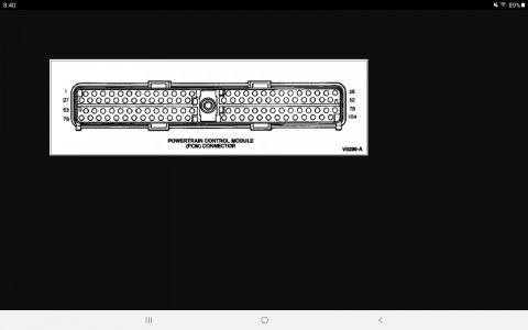
View attachment 28466
PCM Connector Pin-Out Diagram with Circuit Functions in a 96 5.0 and 5.8
Pin Number Circuit Circuit Function
1 315 (P/O) PCM to Transmission Shift Solenoid No. 2
2 658 (P/LG) PCM to Check Engine Indicator Lamp
3 � Not Used
4 � Not Used
5 � Not Used
6 651 (BK/Y) Dedicated Ground
7 � Not Used
8 � Not Used
9 � Not Used
10 � Not Used
11 � Not Used
12 � Not Used
13 107 (P) PCM Flash EEPROM Power Supply
14 784 (LB/BK) 4x4 Low Range Switch to PCM Indicator Lamp
15 915 (PK/LB) J1850 Bus Negative/Data Negative (Return) to PCM
16 914 (T/O) J1850 Bus Positive/Data Positive
17 � Not Used
18 � Not Used
19 � Not Used
20 � Not Used
21 � Not Used
22 � Not Used
23 259 (O/R) Dedicated Ground to TFI Module
24 570 (BK/W) Dedicated Ground � PCM
25 875 (BK/LB) Ground Logic Module
26 � Not Used
27 237 (O/Y) PCM to Transmission Shift Solenoid No. 1
28 � Not Used
29 224 (T/W) Transmission Overdrive Cancel Switch to PCM
30 � Not Used
31 � Not Used
32 � Not Used
33 676 (PK/O) Vehicle Speed Sensor � Negative (Return) to PCM
34 � Not Used
35 392 (P/LG) Heated Exhaust Gas Oxygen Sensor No. 3 to PCM
36 968 (T/LB) Mass Airflow Return
37 923 (O/BK) Transmission Oil Temperature to PCM
38 354 (LG/R) Engine Coolant Temperature Sensor to PCM
39 743 (GY) Air Charge Temperature Sensor to PCM
40 238 (DG/Y) Fuel Pump Monitor to PCM/Fuel Pump Relay to Safety Switch
41 198 (DG/O) A/C Pressure Switch to Control Relay
42 � Not Used
43 � Not Used
44 200 (BR) PCM to Air Management No. 2 (Was TAD)
45 � Not Used
46 � Not Used
47 360 (BR/PK) PCM to Electronic Vacuum Regulator � Constant Current
48 382 (Y/BK) PCM to Test Connector No. 2
49 395 (GY/O) Profile Ignition Pickup to PCM
50 929 (PK) PCM to Spark Angle Pulse Width/Spark Output
51 570 (BK/W) Dedicated Ground � PCM
52 � Not Used
53 924 (BR/O) PCM to Transmission Coast Clutch Solenoid
54 480 (P/Y) PCM to Transmission Converter Clutch Control
55 37 (Y) Battery to Load
56 191 (LG/BK) PCM Top Vapor Management Valve � Constant Current
57 310 (Y/R) Knock Sensor No. 1 to PCM
58 679 (GY/BK) Vehicle Speed Sensor � Positive to PCM
59 917 (DG/LG) Misfire Detection Sensor � Feed
60 74 (GY/LB) Heated Exhaust Gas Oxygen Sensor No. 1 to PCM
61 � Not Used
62 � Not Used
63 � Not Used
64 199 (LB/Y) Manual Lever Position Sensor to PCM
65 352 (BR/LG) Delta Exhaust Pressure Transducer to PCM
66 � Not Used
67 � Not Used
68 � Not Used
69 � Not Used
70 190 (W/O) PCM to Air Management No. 1 (Was TAB)
71 361 (R) Power Output from PCM Relay
72 561 (T/R) PCM to Fuel Injector No. 7 Cylinder
73 559 (T/BK) PCM to Fuel Injector No. 5 Cylinder
74 557 (W) PCM to Fuel Injector No. 3 Cylinder
75 555 (T) PCM to Fuel Injector No. 1 Cylinder or Bank No. 1
76 570 (BK/W) Dedicated Ground � PCM
77 570 (BK/W) Dedicated Ground � PCM
78 � Not Used
79 911 (W/LG) PCM to Output Circuit Indicator Lamp/Overdrive Cancel Indicator
80 926 (LG/O) PCM to Fuel Pump Relay Control
81 925 (W/Y) PCM to Electronic Pressure Control No. 1
82 � Not Used
83 264 (W/LB) PCM to Idle Speed Control Motor No. 1
84 136 (DB/Y) Output Shaft Speed to PCM
85 � Not Used
86 � Not Used
87 94 (R/BK) Heated Exhaust Gas Oxygen Sensor No. 2 to PCM
88 967 (LB/R) Mass Air Flow Sensor to PCM
89 355 (GY/W) Throttle Position Sensor to PCM/Diesel Fuel Injector Pump Lever Sensor
90 351 (BR/W) Power to Engine Sensors
91 359 (GY/R) Sensor Signal Return
92 511 (LG) Stoplamp (Brake On/Off) Switch to Stoplamps
93 387 (R/W) HEGO Sensor Heater Voltage Monitor No. 1 to PCM
94 388 (Y/LB) HEGO Sensor Heater Voltage Monitor No. 2 to PCM
95 389 (W/BK) HEGO Sensor Heater Voltage Monitor No. 3 to PCM
96 � Not Used
97 361 (R) Power Output from PCM Relay
98 562 (LB) PCM to Fuel Injector No. 8 Cylinder
99 560 (LG/O) PCM to Fuel Injector No. 6 Cylinder
100 558 (BR/LB) PCM to Fuel Injector No. 4 Cylinder
101 556 (W) PCM to Fuel Injector No. 2 Cylinder or Bank No. 2
102 � Not Used
103 570 (BK/W) Dedicated Ground � PCM
104 � Not Used


