Steering wheel not straight after steering box replacement

Disclaimer: Links on this page pointing to Amazon, eBay and other sites may include affiliate code. If you click them and make a purchase, we may earn a small commission.

tjg8675

Member
Joined
Sep 3, 2007
Messages
92
Reaction score
4
Hi all,

I replaced my steering box yesterday for the 2nd time this year (first box was still loose), I followed the same procedures as the 1st time except this time I had to remove the drag link from the pitman arm and remove the pitman arm from the steering box with the steering box removed from the vehicle, long story...I couldn't get the pitman arm puller on because the pitman arm was too close to steering gear and the puller wouldn't fit...had to use some persuasion in the form of a BFH (big freakin' hammer).

So after a little persuasion I got the pitman arm off and everything reassembled. it all went together just fine except now my steering wheel points to about 1:30 when going straight down the road. I did not have this problem last time and am sure all the correct placement of notches was made (steering shaft to steering gear & steering gear to pitman arm) could this be an issue with the steering box not being straight or is it just an issue for the alignment shop? (I just had it aligned...three times as a matter of fact, once after getting new tires, second time after camber sleeve installed, third after new axle pivot bushings installed...so I know alignment was good before the steering gear swap).

Thanks for any help

 
OP
OP
tjg8675

tjg8675

Member
Joined
Sep 3, 2007
Messages
92
Reaction score
4
Hi miesk5,

Yes everything was lined up straight and locked during disassembly and reassembly. All notches lined up same as they did the first time. Only big difference this time was I had to take drag link off pitman arm. 


miesk5

96 Bronco 5.0
Staff member
Moderator
Joined
Oct 18, 2005
Messages
9,078
Reaction score
1,035
Location
Floating in the Pacific
Yo t,

Following by Ford;


  • Clear Vision Complaint — Steering Wheel Spokes Obscure View of Instrument Panel with Wheels in Straight-Ahead Position


  • Damaged or twisted steering gear sector shaft.


  • REPLACE steering gear sector shaft.


  • Toe out of adjustment.


  • ADJUST toe setting.


OP
OP
tjg8675

tjg8675

Member
Joined
Sep 3, 2007
Messages
92
Reaction score
4
Hi miesk5,

Thanks for the info,

Wondering if it's possible that something in the steering gear, steering shaft or column got bent when torquing pitman arm nut (torqued to 210ftlbs haynes spec said 190-230ftlbs)?

Thanks again for your help

 
Last edited by a moderator:

miesk5

96 Bronco 5.0
Staff member
Moderator
Joined
Oct 18, 2005
Messages
9,078
Reaction score
1,035
Location
Floating in the Pacific
Yo t,

Following by Ford;

"Recheck torque readings and replace the steering gear sector shaft arm. Tighten the pitman arm-to-sector shaft nut 230-310 Nm (170-228 lb-ft)." In a 96, but same for your 95.

 
OP
OP
tjg8675

tjg8675

Member
Joined
Sep 3, 2007
Messages
92
Reaction score
4
Hi miesk5,

Is it ok to torque that when in the vehicle? Or should that be done off the vehicle?

Thanks again


miesk5

96 Bronco 5.0
Staff member
Moderator
Joined
Oct 18, 2005
Messages
9,078
Reaction score
1,035
Location
Floating in the Pacific
Yo T,

Sorry, we have a bad comcast connection.


In-Vehicle Adjustment


SPECIAL SERVICE TOOL(S) REQUIRED


Description


Tool Number


Pitman Arm Puller


T64P-3590-F


Adjust total on center load to eliminate excessive lash between the sector and rack teeth as follows.

  1. With the engine (6007) off, turn the steering wheel (3600) from full right stop to full left stop at least once.

  1. Refer to Section 11-04 for proper steering wheel hub cover removal procedure.

  1. Disconnect the steering gear sector shaft arm (3590) from the steering gear sector shaft (3575) using Pitman Arm Puller T64P-3590-F.

  1. Attach a newton meter (pound-inch) torque wrench to the steering wheel hub nut and determine the torque required to rotate the power steering gear input shaft and control (3D517) back and forth across the center position (± 90 degrees).

  1. Reset the meshload only if the measured torque for total on-center load is less than 1.5 Nm (13 lb-in). If reset is required, loosen the adjuster lock nut and turn the sector shaft adjuster ***** until the measured total on-center load torque is 2.0 Nm (18 lb-in). Hold the sector shaft ***** in place and tighten the lock nut to 48-61 Nm (35-45 lb-ft).

  1. Recheck torque readings and replace the steering gear sector shaft arm. Tighten the pitman arm-to-sector shaft nut 230-310 Nm (170-228 lb-ft).

  1. Verify no binding condition in steering throughout full stop-to-stop travel. Verify customer concern is resolved.

  1. Replace steering wheel hub cover.


More Ford gear info for posterity:


Steering Gear  NOTE: Do not use solvent on seals. Using a clean workbench and tools, thoroughly clean the exterior of the gear with solvent. Drain off excess hydraulic fluid, if necessary.


NOTE: Handle all parts carefully to avoid nicks, burrs, scratches and dirt.


SPECIAL SERVICE TOOL(S) REQUIRED


Description


Tool Number


Bench Mounted Holding Fixture


T57L-500-B


Adjuster and Lock Nut Wrench


T66P-3553-B


Valve Housing to Piston Spacer


T66P-3553-C


Disassembly

  1. Hold the steering gear (3504) upside down over a drain pan and cycle the power steering gear input shaft and control (3D517) several times to drain the fluid from the steering gear.

  1. NOTE: The indexing flat on the power steering gear input shaft and control should be facing downward.

    Secure the steering gear in a soft-jawed vise.
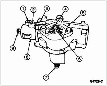
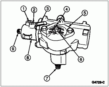
    g4728c.gif


    Item


    Part Number


    Description


    1


    Outlet Port (Part of 3504)


    2


    Inlet Port (Part of 3504)


    3


    Identification Tag
    (Part of 3504)


    4


    Sector Shaft Adjusting ***** (Part of 3540)


    5


    3580


    Steering Gear Sector Shaft Housing Cover


    6


    Lock Nut (Part of 3540)


    7


    3575


    Steering Gear Sector Shaft


    8


    Control Valve Housing
    (Part of 3568)


    9


    3D517


    Power Steering Gear Input Shaft and Control


  1. Turn the power steering gear input shaft and control to either stop, then turn it back two turns to center the steering gear.

  1. Remove bolts to the steering gear sector shaft housing cover (3580).

  1. Tap the lower end of the steering gear sector shaft (3575) with a soft hammer to loosen it, and lift the steering gear housing end cover (3568) and steering gear sector shaft from the housing as an assembly. Discard the power steering gear control valve housing o-ring (3756).

  1. NOTE: This step is required only when it is necessary to remove the steering gear sector shaft from the sector assembly.

    Remove the nut from the sector shaft adjusting *****. Turn the steering gear sector shaft housing cover counterclockwise and remove it from the sector shaft adjuster *****.

  1. Remove the valve housing attaching bolts and identification tag. Lift the valve housing off the steering gear housing (3548). Remove the valve housing, piston assembly and steering gear sector shaft housing cover gasket (3581). Discard the gasket.

  1. NOTE: If valve housing or the power steering gear input shaft seals (3D526) are to be replaced, proceed to Step 11. If steering gear sector shaft housing oil seal (3591) is to be replaced go to Steering Gear Housing in the Disassembly and Assembly portion of this section. Steering gear worm ball (3647) needs to be removed if power steering gear input shaft seal is to be replaced.

    With the piston held so the steering gear ball return guide (3523) faces up, remove the ball guide clamp screws and steering gear ball return guide clamp (3544).

  1. With a finger over the opening in the steering gear ball return guide, turn the piston so the steering gear ball return guide faces down over a clean container. Let the steering gear ball return guide drop into the container.
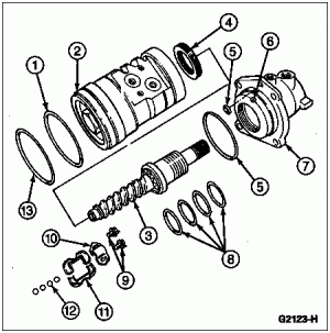
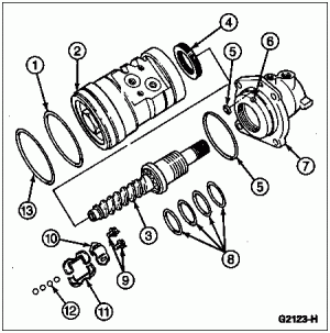
    g2123h.gif


    Item


    Part Number


    Description


    1


    Piston Ring (Part of 3E502)


    2


    Piston (Part of 3D517)


    3


    3D517


    Power Steering Gear Input Shaft and Control


    4


    3D627


    Power Steering Gear Race Nut


    5


    O-Ring (Part of 3D517)


    6


    382095-S


    Race Lock Nut Setscrew


    7


    Valve Housing
    (Part of 3504)


    8


    Valve Sleeve Seals
    (Part of 3D517)


    9


    388889-S


    Screws


    10


    3544


    Steering Gear Ball Return Guide Clamp


    11


    3523


    Steering Gear Ball Return Guide


    12


    3647


    Steering Gear Worm Ball


    13


    3805


    Power Steering Gear Piston Seal


  1. Rotate the power steering gear input shaft and control from stop to stop until all balls fall from the piston into the container. The power steering gear input shaft and control can then be removed from the piston. Inspect the piston bore to make sure all steering gear worm balls have been removed.

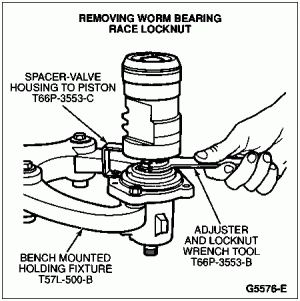
  1. Install the power steering gear input shaft and control in the Bench Mounted Holding Fixture T57L-500-B and loosen the Allen head race lock nut ***** from the valve housing.

  1. Remove the power steering gear race nut (3D627) using Adjuster and Lock Nut Wrench T66P-3553-B and Valve Housing to Piston Spacer T66P-3553-C.

  1. Carefully slide the power steering gear input shaft and control and steering gear input worm gear and rack (3524) out of the valve housing.
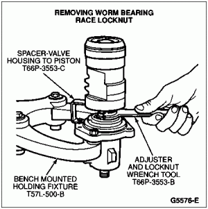
    g5576e.gif
     

Assembly

  1. Mount the power steering gear input shaft and control in the Bench Mounted Holding Fixture T57L-500-B with the flanged end up.

  1. Apply a light coat of Premium Power Steering Fluid E6AZ-19582-AA or equivalent meeting Ford specification ESW-M2C33-F to the Teflon® rings on the valve sleeve.

  1. Carefully install the power steering gear input shaft and control valve in the steering gear housing.

  1. Install the power steering gear race nut in the housing and tighten to 75-122 Nm (55-90 lb-ft).

  1. Install the Allen head race lock nut setscrew through the valve housing and tighten to 1.7-2.8 Nm (15-25 lb-in).

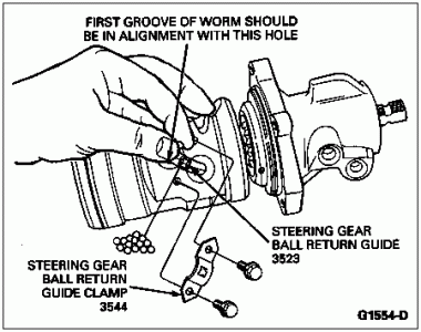
  1. Place the piston on the bench with the ball guide holes facing up. Insert the power steering gear input shaft and control into the piston so the first groove is in line with the hole nearest the center of the piston.

  1. Place the steering gear ball return guide in the piston. Turning the power steering gear input shaft and control counterclockwise, place the same steering gear worm balls as were removed in the steering gear ball return guide. During assembly, 27 to 29 balls are required. If all the balls have not been inserted upon reaching the left stop, rotate the power steering gear input shaft and control in one direction then the other while inserting the remaining balls.
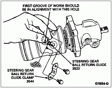
    g1554d.gif
     

  1. Secure the guides in the ball nut with the clamp. Tighten screws to 5-7 Nm (42-70 lb-in).

  1. Apply petroleum jelly or equivalent to the Teflon® seal on the piston.

  1. Place a new steering gear sector shaft housing cover gasket on the valve housing.

  1. Slide the piston and valve into the steering gear housing being careful not to damage the piston ring.

  1. Align the oil passage in the steering gear ball return guide with the passage in the steering gear housing. Place a new O-ring onto the oil passage hole of the steering gear housing. Install identification tag onto the housing. Install, but do not tighten, the attaching bolts. Identification tag is to be installed under upper right valve housing bolt.

  1. Rotate the piston so the teeth are in the same plane as the steering gear sector shaft. Tighten the valve housing attaching bolts to 40-60 Nm (30-44 lb-ft).

  1. Position the steering gear sector shaft housing oil seal in the steering gear housing. Turn the input shaft to center the piston.

  1. Apply petroleum jelly or equivalent to the sector shaft journal, and position the sector shaft and cover assembly in the gear housing. Install the steering gear housing end cover attaching bolts. Tighten the bolts to 75-94 Nm (55-69 lb-ft).

  1. Attach a pound-inch torque wrench to the power steering gear input shaft. Adjust meshload to specification. Refer to Specifications at the end of this section.
 
Last edited by a moderator:

Shaggy

Active member
Staff member
Administrator
Moderator
Joined
Sep 19, 2019
Messages
209
Reaction score
112
Location
Arizona
Yo T,

Sorry, we have a bad comcast connection.


In-Vehicle Adjustment


SPECIAL SERVICE TOOL(S) REQUIRED


Description


Tool Number


Pitman Arm Puller


T64P-3590-F


Adjust total on center load to eliminate excessive lash between the sector and rack teeth as follows.

  1. With the engine (6007) off, turn the steering wheel (3600) from full right stop to full left stop at least once.

  1. Refer to Section 11-04 for proper steering wheel hub cover removal procedure.

  1. Disconnect the steering gear sector shaft arm (3590) from the steering gear sector shaft (3575) using Pitman Arm Puller T64P-3590-F.

  1. Attach a newton meter (pound-inch) torque wrench to the steering wheel hub nut and determine the torque required to rotate the power steering gear input shaft and control (3D517) back and forth across the center position (± 90 degrees).

  1. Reset the meshload only if the measured torque for total on-center load is less than 1.5 Nm (13 lb-in). If reset is required, loosen the adjuster lock nut and turn the sector shaft adjuster ***** until the measured total on-center load torque is 2.0 Nm (18 lb-in). Hold the sector shaft ***** in place and tighten the lock nut to 48-61 Nm (35-45 lb-ft).

  1. Recheck torque readings and replace the steering gear sector shaft arm. Tighten the pitman arm-to-sector shaft nut 230-310 Nm (170-228 lb-ft).

  1. Verify no binding condition in steering throughout full stop-to-stop travel. Verify customer concern is resolved.

  1. Replace steering wheel hub cover.


More Ford gear info for posterity:


Steering Gear  NOTE: Do not use solvent on seals. Using a clean workbench and tools, thoroughly clean the exterior of the gear with solvent. Drain off excess hydraulic fluid, if necessary.


NOTE: Handle all parts carefully to avoid nicks, burrs, scratches and dirt.


SPECIAL SERVICE TOOL(S) REQUIRED


Description


Tool Number


Bench Mounted Holding Fixture


T57L-500-B


Adjuster and Lock Nut Wrench


T66P-3553-B


Valve Housing to Piston Spacer


T66P-3553-C


Disassembly

  1. Hold the steering gear (3504) upside down over a drain pan and cycle the power steering gear input shaft and control (3D517) several times to drain the fluid from the steering gear.

  1. NOTE: The indexing flat on the power steering gear input shaft and control should be facing downward.

    Secure the steering gear in a soft-jawed vise.

    g4728c.gif


    Item


    Part Number


    Description


    1


    Outlet Port (Part of 3504)


    2


    Inlet Port (Part of 3504)


    3


    Identification Tag
    (Part of 3504)


    4


    Sector Shaft Adjusting ***** (Part of 3540)


    5


    3580


    Steering Gear Sector Shaft Housing Cover


    6


    Lock Nut (Part of 3540)


    7


    3575


    Steering Gear Sector Shaft


    8


    Control Valve Housing
    (Part of 3568)


    9


    3D517


    Power Steering Gear Input Shaft and Control


  1. Turn the power steering gear input shaft and control to either stop, then turn it back two turns to center the steering gear.

  1. Remove bolts to the steering gear sector shaft housing cover (3580).

  1. Tap the lower end of the steering gear sector shaft (3575) with a soft hammer to loosen it, and lift the steering gear housing end cover (3568) and steering gear sector shaft from the housing as an assembly. Discard the power steering gear control valve housing o-ring (3756).

  1. NOTE: This step is required only when it is necessary to remove the steering gear sector shaft from the sector assembly.

    Remove the nut from the sector shaft adjusting *****. Turn the steering gear sector shaft housing cover counterclockwise and remove it from the sector shaft adjuster *****.

  1. Remove the valve housing attaching bolts and identification tag. Lift the valve housing off the steering gear housing (3548). Remove the valve housing, piston assembly and steering gear sector shaft housing cover gasket (3581). Discard the gasket.

  1. NOTE: If valve housing or the power steering gear input shaft seals (3D526) are to be replaced, proceed to Step 11. If steering gear sector shaft housing oil seal (3591) is to be replaced go to Steering Gear Housing in the Disassembly and Assembly portion of this section. Steering gear worm ball (3647) needs to be removed if power steering gear input shaft seal is to be replaced.

    With the piston held so the steering gear ball return guide (3523) faces up, remove the ball guide clamp screws and steering gear ball return guide clamp (3544).

  1. With a finger over the opening in the steering gear ball return guide, turn the piston so the steering gear ball return guide faces down over a clean container. Let the steering gear ball return guide drop into the container.

    g2123h.gif


    Item


    Part Number


    Description


    1


    Piston Ring (Part of 3E502)


    2


    Piston (Part of 3D517)


    3


    3D517


    Power Steering Gear Input Shaft and Control


    4


    3D627


    Power Steering Gear Race Nut


    5


    O-Ring (Part of 3D517)


    6


    382095-S


    Race Lock Nut Setscrew


    7


    Valve Housing
    (Part of 3504)


    8


    Valve Sleeve Seals
    (Part of 3D517)


    9


    388889-S


    Screws


    10


    3544


    Steering Gear Ball Return Guide Clamp


    11


    3523


    Steering Gear Ball Return Guide


    12


    3647


    Steering Gear Worm Ball


    13


    3805


    Power Steering Gear Piston Seal


  1. Rotate the power steering gear input shaft and control from stop to stop until all balls fall from the piston into the container. The power steering gear input shaft and control can then be removed from the piston. Inspect the piston bore to make sure all steering gear worm balls have been removed.

  1. Install the power steering gear input shaft and control in the Bench Mounted Holding Fixture T57L-500-B and loosen the Allen head race lock nut ***** from the valve housing.

  1. Remove the power steering gear race nut (3D627) using Adjuster and Lock Nut Wrench T66P-3553-B and Valve Housing to Piston Spacer T66P-3553-C.

  1. Carefully slide the power steering gear input shaft and control and steering gear input worm gear and rack (3524) out of the valve housing.

    g5576e.gif
     

Assembly

  1. Mount the power steering gear input shaft and control in the Bench Mounted Holding Fixture T57L-500-B with the flanged end up.

  1. Apply a light coat of Premium Power Steering Fluid E6AZ-19582-AA or equivalent meeting Ford specification ESW-M2C33-F to the Teflon® rings on the valve sleeve.

  1. Carefully install the power steering gear input shaft and control valve in the steering gear housing.

  1. Install the power steering gear race nut in the housing and tighten to 75-122 Nm (55-90 lb-ft).

  1. Install the Allen head race lock nut setscrew through the valve housing and tighten to 1.7-2.8 Nm (15-25 lb-in).

  1. Place the piston on the bench with the ball guide holes facing up. Insert the power steering gear input shaft and control into the piston so the first groove is in line with the hole nearest the center of the piston.

  1. Place the steering gear ball return guide in the piston. Turning the power steering gear input shaft and control counterclockwise, place the same steering gear worm balls as were removed in the steering gear ball return guide. During assembly, 27 to 29 balls are required. If all the balls have not been inserted upon reaching the left stop, rotate the power steering gear input shaft and control in one direction then the other while inserting the remaining balls.

    g1554d.gif
     

  1. Secure the guides in the ball nut with the clamp. Tighten screws to 5-7 Nm (42-70 lb-in).

  1. Apply petroleum jelly or equivalent to the Teflon® seal on the piston.

  1. Place a new steering gear sector shaft housing cover gasket on the valve housing.

  1. Slide the piston and valve into the steering gear housing being careful not to damage the piston ring.

  1. Align the oil passage in the steering gear ball return guide with the passage in the steering gear housing. Place a new O-ring onto the oil passage hole of the steering gear housing. Install identification tag onto the housing. Install, but do not tighten, the attaching bolts. Identification tag is to be installed under upper right valve housing bolt.

  1. Rotate the piston so the teeth are in the same plane as the steering gear sector shaft. Tighten the valve housing attaching bolts to 40-60 Nm (30-44 lb-ft).

  1. Position the steering gear sector shaft housing oil seal in the steering gear housing. Turn the input shaft to center the piston.

  1. Apply petroleum jelly or equivalent to the sector shaft journal, and position the sector shaft and cover assembly in the gear housing. Install the steering gear housing end cover attaching bolts. Tighten the bolts to 75-94 Nm (55-69 lb-ft).

  1. Attach a pound-inch torque wrench to the power steering gear input shaft. Adjust meshload to specification. Refer to Specifications at the end of this section.
Awesome post miesk5!!

 
OP
OP
tjg8675

tjg8675

Member
Joined
Sep 3, 2007
Messages
92
Reaction score
4
Hi,
Just to follow up on this I got it aligned and all seems ok...
Thanks miesk5 for the help
 

Members online

No members online now.

Latest posts

Forum statistics

Threads
22,617
Messages
136,650
Members
25,267
Latest member
Broncodad86
Top