Yo,
Finally got the following:
87-92 Broncos have Rear Wheel Antilock Brakes (RABS). Sometimes it can cause the rear brakes to drag, & is one of the things to check if they do. There's a self test procedure for the system described below, followed by testing procedures & flashout codes. If both the Red & Yellow lights are lit, start with section "C" below before following the info obtained from the codes. -by ElKabong at FS
Pulling RABS Flashout Code:
This routine should be good from 87-92.
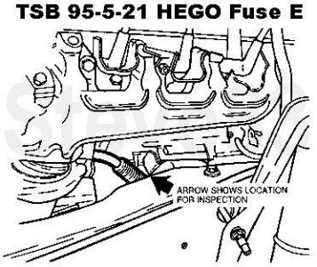
On my 90, the test connector comes out of a large loom under the dash, coming through the firewall, near the parking brake. On mine there are 2 similar connectors in that area, the correct one has only 1 black wire with an orange tracer running to it, & was hidden on top of the loom. The correct one is hanging down on the bottom right of the 90 pic below. 92 has the test plug on the passenger side. See jermil01's 92 pics below.
After you've grounded & ungrounded the wire, the yellow abs light starts to flash. Count the flashes. It said to not count the 1st series, because it may start in the middle. The last flash of the series is a long flash. Then it repeats over & over, until you turn the key off.
Count all of the short flashes & the long one together (So 4 short & 1 long is code #5). If I remember right, it should be a number between 2 & 15 or so. In
Steve83's Brakes & Hubs album, he has the code definitions & other info for RABS & RABS-II about 7/8 of the way down the page. Make sure you look at the RABS codes, not the 4WABS codes. Or go to
Steve83's RABS code definitions direct link.
There are also more testing instructions in the manual that I can look up after you know what the code is, & whether the red brake light is on or off.
92 Test Connector
Pic from
@jermil01
 92 Module
From
@jermil01 "And the RABS module behind the glove box".
 C Testing Procedure:
From the 1990 Ford Truck Shop Manual.
Use this section when both Yellow & Red lights are on.
Test C
Yellow ANTILOCK light On and
Red BRAKE Light On
C1 -Low brake fluid
Brake fluid level ok = Go to test C2
Brake fluid level low = Check for fluid leaks & repair. Fill system
C2 -Master cylinder float -Check float for buoyancy
1- Remove cap from master cylinder.
2-Using a clean steel implement, push down on float in reservoir.
Float moves down = Go to test C3
Float does not move down (Sits at the bottom of the reservoir) = Replace master cylinder reservoir.
C3 -Diode/resistor element -Check for proper functioning of the diode/resistor element.
1- Turn ignition key to the on position.
2- Check parking brake & release if applied.
Both ANTILOCK & BRAKE warning lamps go off = Replace RABS diode/resistor element.
Both ANTILOCK & BRAKE warning lamps stay on = Go to test C4.
C4 -Diode resistor element continued -Continue to check for proper functioning of the diode/resistor element.
1- Remove the parking brake switch & the diesel low vacuum switch, if so equipped.
Both ANTILOCK & BRAKE warning lamps go off = Replace RABS diode/resistor element.
Both ANTILOCK & BRAKE warning lamps stay on = Go to test C5
C5 -Antilock valve switch (Pull Codes)
-Obtain the flashout code as described in Diagnosis & Testing in this section.
(See the section above for pulling RABS codes)
Flashout code is obtained = Refer to Flashout Codes Charts
ANTILOCK & BRAKE warning lamps stay on steady = Go to test C6
C6 -Master cylinder switch
-Check for the proper functioning of the master cylinder level indicator switch.
1- Remove the connector from the master cylinder.
2- Connect a jumper wire between the 2 purple/white wires in the connector.
3- Turn the ignition key to the on position.
ANTILOCK & BRAKE warning lamps stay on = Go to test C7
ANTILOCK & BRAKE warning lamps go off = Replace the master cylinder reservoir.
C7 -Brake Light Wiring
-Check for shorts in brake light wiring.
1- Disconnect module harness connector from module
2- Turn ignition key to the on position.
Antilock light goes off & Brake light stays on = Check for short to ground in the 977 circuit. Refer to wiring diagram in this section.
Both ANTILOCK & BRAKE warning lamps go off = Replace module.
D Testing Procedure
From the 1990 Ford Truck Shop Manual.
Use this section when Yellow ANTILOCK light is on & Red BRAKE light is off.
Test D
Yellow ANTILOCK light On and
Red BRAKE Light Off
D1 -Obtain the Flashout Code as described in Diagnosis & Testing in this section.
(See the section above for pulling RABS codes)
Flashout code cannot be obtained = Go to test D2.
Flashout Code is obtained = Refer to the Flashout Code charts.
D2 -Master Cylinder Connector
Make sure master cylinder connector is fully plugged in.
Master cylinder connector is not fully plugged in = Plug in the master cylinder connector.
Master cylinder connector is plugged in = Go to test D3.
D3 -RABS 20 Amp Fuse
-Remove & inspect the RABS 20 amp fuse.
Fuse is OK = Replace fuse. Go to test D4.
Fuse is blown = Short to ground between the fuse & the module wiring harness. Repair short in the 601 circuit & replace the 20 amp fuse. Refer to the wiring diagrams in this section.
D4 -Shorts in Module Harness Connector Wiring
-Check for wiring short to ground.
1- Turn ignition switch to the "on" position.
2- Remove the module harness connector from the module.
3- Observe the REAR ANTILOCK light.
Light goes off = Go to test D5.
Light remains on = Check for a short in the 603 circuit. Refer to the wiring diagram in this section.
D5 -Power to the module
-Check for an open in the circuit supplying power to the module.
1- Set the voltmeter on the 20 VDC scale.
2- Turn ignition switch to the "on" position.
3- Measure the voltage between pin 1 (or pin 9) and chassis ground.

Voltage less than 9v = Repair the open in the 601 circuit or power to the fuse panel. See Wiring Diagram.
Voltage greater than 9v = Go to test D6.
D6 -Voltage at the Fluid Level Circuit
-Check the voltage from the fluid level circuit.
1- Set the voltmeter on the 20 VDC scale.
2- Turn ignition switch to the "on" position.
3- Measure the voltage between pin 2 and chassis ground.

Voltage less than 8v = Go to test D7.
Voltage greater than 8v = Go to test D8.
D7 -Fluid Level Sensor and Wiring
-Check the voltage at the fluid level circuit.
1- Set the voltmeter on the 20 VDC scale.
2- Turn ignition switch to the "on" position.
3- Measure the voltage at each of the purple/white wires at the back of the master cylinder fluid level switch connector without disconnecting the connector.
Voltage greater than 8v at both wires = Check for open in 977 circuit.
Voltage less than 8v at both wires = Replace diode resistor element or open in 640 circuit.
Voltage greater than 8v at one wire and less than 8v at the other wire = Change the master cylinder reservoir. Refer to section 12-30, Brake Pedal, Master Cylinder and Valves for procedure.
D8 -Grounded Diagnostic Lead
-Check the voltage at the diagnostic lead
(See the 90 or 92 "Test Connector" pic above).
1- Reconnect the module harness connector.
2- Set the voltmeter on the 20 VDC scale.
3- Turn ignition switch to the "on" position.
4- Measure the voltage between the diagnostic lead and chassis ground.
Voltage is less than 1v = Check for a short in the 571 diagnostic circuit. If no short is found, go to test D9.
Voltage is greater than 1v = Go to test D9.
D9 -Computer Module
-Replace computer module and retest.
Flashout Code 4
Yellow REAR ANTILOCK Light Flashes 4 Times
Red Brake Warning Light Illuminated
RABS Valve Switch Closed
4a -Check for closed RABS valve switch
1-Disconnect RABS valve harness connector from valve connector.
2- Place ohmmeter on the 20k ohms scale.
3-Check resistance between valve connector switch pin & valve body.
Valve connector -Pin View
. . . . . . . . . . .. .. .... . . .
_
. . . . . . . ... . . . .... .. ./>. O.>.\
Valve switch pin ---l-O >..O>l
. . . . . . . .... . . . . .. . l . ..O... .l
. . . . . . . .
l. .. .. .l_______l
. . . . . . . .. . . .____
. . . . . . . . . . . . ._
Resistance is greater than 10k ohms = Go to test 4b.
Resistance is less than 10k ohms = Replace RABS valve
4b Check for short between RABS ground switch & valve ground lead
1- Set the ohmmeter on 20k ohm scale.
2- Check resistance between the valve connector switch pin and valve solenoid ground pin.
Valve connector -Pin View
. . . . . . . . . . .. . . . .. ... .
__
. . . . . . . . . . . .. . .... . ./ O \
Valve switch pin ----lO->Ol
Valve sol ground----I--O I
. . . . . . ... . . . . . . . .. .l______l
Resistance is greater than 10k ohms = Go to test 4c.
Resistance is less than 10k ohms = Replace RABS valve
4c Check for rabs valve switch wire shorted to ground or module
1- Disconnect battery.
2- Set the ohmmeter on the 200k ohm scale.
3- Disconnect the module harness from the module.
4- Check the resistance between harness connector pin 6 and chassis ground.
Module harness connector -Pin view
View attachment 221149
Resistance is greater than 100k ohms = Replace computer module.
Resistance is less than 100k ohms = Repair short in 535 circuit, valve switch wire from valve to computer module.