Yo tjg8675,
Here ya go:
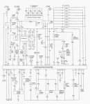
The locations of the connectors along the path from VSS to 4WABS and up to Instr Cluster & PSOM are;

To help identify the connectors:
C404 VSS On rear axle sensor (A7) Terminals: 02
to
C205 Male and Female Pins 10 &!16 @ LH rear of engine compartment, in safety wall (Fire Wall) Terminals: 24 In-Line
to
C202 F & M Pins 46 z& 47 @ LH rear of engine compartment, in safety wall (A8) Terminal: 7 In-Line
to
C119 Pins 21 & 22 @ LH front corner of engine compartment on 4WABS control module (E10),Terminals: 40; through module
& out:
O/LB to C202 F & M pin 58 @ LH rear of engine compartment, in safety wall (A8) Terminal: 7 In-Line to C252 PSOM Pin 4
LG/Y to Splice S107 Engine control sensor harness, from C119 near T/O to G101 (G101 RH side of Radiator support); & to C202 pin 69 to PSOM Pin 5
C252 is for Programmable Speedometer/Odometer Module (PSOM), Behind top LH side of I/P, on PSOM (A7) Terminal: 12 Color: B
C202 F and M and spliced to Ground G100 (BK)
G100 & G104 (tied together in diagram) G100 @ LH front of engine compartment, on upper radiator support
G100 Serves Component:
Fuel Pump Module
Inertia Fuel Shutoff
Misfire Sensor aka crankshaft position sensor
Misfire Sensor Shield
Output Shaft Speed (OSS) Sensor
Powertrain Control Module (PCM), 5.0L
G200 Behind bottom of RH cowl panel
Serves Component:
Air Bag Diagnostic Monitor
Electronic Shift Control Module
Instrument Cluster
Programmable Speedometer/Odometer Module (PSOM)
Remote/Keyless Entry Module
Speed Control Servo/Amplifier Assembly
From PSOM C252 Pin 7 (GY/BK) to Splice S231 Main harness, near T/O to speed control amplifier to C202 pin 21 to Splice 246 to PCM pin 3 and to Speed Control Servo Amplifier Connector C216 pin 3.
...
C185 PK/O @ PCM 96 Bronco 5.0L Powertrain Control Module (PCM) LH side of safety wall, on powertrain control module (PCM) (C10) Terminal: 104 Color: GY
C185, 96 Bronco 5.8L Powertrain Control Module (PCM) LH side of safety wall, on powertrain control module (PCM) (C10) Terminal: 104 Color: GY
C185 @PCM to C202 F and M
Splice 216 to Ground G200, Instrument Cluster ground is inside passenger side kick panel
and on to C185 @ PCM PIN 58 (GY/BK) and from Pin 46 to MLPS (TR) Pin 2
I am using a tablet without split screen, can you compare the diagram at top to my narrative?
I originally did this for my 96, so your 95 may have some differences in connectors, splices and pin numbers.


