This is a complete walk through for a hydro-boost installation on an early (66-77) Bronco with power steering. I will try to be as detailed as possible, but if anyone has questions, please feel free to ask me. I did this installation over the past couple of days and it is fresh in my mind, so I won't leave anything out. I also have the power steering unit that was originally on a 73-75 Bronco, but the same directions should be able to be used for any PS set up. I used a 1990 Chevy Astro Van as my donor vehicle. The parts I took were the hydro-boost unit, master cylinder, proportioning valve, steel lines between the master cylinder & proportioning valve, and both high pressure hoses attached to the hydro-boost unit.
Car & Misc. Parts Needed:
Astro Van Hydro-Boost Unit, 90-94 (HB)
Astro Van Master Cylinder, same years (MC)
Astro Van High Pressure Supply Hose (from PS pump)
Astro Van High Pressure HB to PS Box Hose
Astro Van Steel Lines from MC to Proportioning Valve (PV)
Astro Van Proportioning Valve (optional)
Bronco High Pressure Power Steering Hose
Stainless Steel Brake Lines, 50" (or close - 2 different sizes needed)
2-4 feet of 3/8" Power Steering Hose
Bronco MC Push Rod
3/8" Brass "T" Connection
5-10 hose clamps
3/8-16 or 3/8-24 thread by 1.5" coupler nut
*NOTE: I did not reuse the AV MC. I used it as a core and took it back for a remanufactured unit. The HB unit should still be in good shape unless your donor vehicle was damaged in the front end.
Dismantle, Prep & Installation:
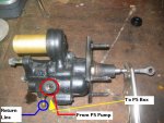
You are going to need to have new high pressure hoses made up to adapt the Chevy parts to the Ford parts. Take the three high pressure hoses to a local hydraulic fitting shop and have them make you two new ones. You will need to match them up as follows. The PS pump end off the Bronco hose will attach to the single valve inlet on the HB unit (this is the port on the same side as the gold fluid reservoir is on). This is the supply line to the HB unit. The other end of the Bronco hose, the PS box end, will attach to the hose from the opposite side of the HB unit (the side with the brass nozzle/hose attachment). These are two different fittings that are on the HB unit, so do not get them mixed up or it will not work correctly. The last port on the HB unit (the brass nozzle/hose attachment) is a low pressure return line that will go back to the PS pump.
Remove the original MC, steel lines to PV, PV & front steel line to termination block on the frame. You must replace all steel lines from the PV to the MC, and I replaced the front steel line from the PV to the front termination block on the frame. This might also be a good time to replace your front brake line from the termination block to the axle.
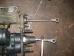
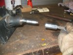
Once all things are removed and out of the way, you will see that the original MC push rod is longer than the HB push rod. Both of these should be 3/8" rods. Mine had a difference of 1 1/4" in length. Here you will need to cut the HB push rod & the EB MC rod. I cut the HB rod as close to the pedal attachment as possible. The EB MC rod was cut about 1.5" down from the pedal attachment. I threaded both with 3/8-16 threads, but for a finer adjustment, I would recommend 3/8-24. Once you have the two push rods threaded and are able to connect them together, set your HB unit aside until ready for installation.
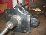
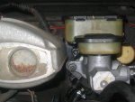
For this installation, the HB unit will have to be flipped upside down. On the AV, the fluid reservoir is on the passenger side of the unit and here we will be installing it exactly 180 degrees opposite with that reservoir on the driver side. Measure the base of the plunger housing (right up next to the mounting plate) on the HB unit and the original MC hole in the firewall. The firewall hole will need to be opened up to fit the HB unit. I used air & a grinding stone to open it up, which took me about 10 minutes of grinding & checking progress. At this time, knock the pressed in bolts out of the HB mounting plate, and with some card stock thickness paper, make a template of the mounting plate. Try and get this as accurate as possible to get the best possible fit. Once you have your template made, measure it against the fire wall. The HB mounting plate will overlap the dust boot on the steering column. Mark the overlap on your template and cut it out. Take this back to the HB unit and mark it and cut the mounting plate to give yourself clearance. You will lose one mounting bolt, but that is ok, you WILL NOT be putting the pressure on this unit you would be on a stock MC. Once you have the HB unit cut to clear the dust boot, put it up to the firewall & mark where to drill your holes for the bolts. Check this with your template as well to be sure. You will end up drilling three holes through the pedal assembly bracket, so this just gives you added strength. You will have to notice that there is a body/firewall seam running vertical that the HB unit will not fit over or beside. Here is where I had to do some thinking because I am running an EFI set up. I took and put 2 washers under the HB mounting bracket on that side only to give me clearance of my EFI plenum. You can notch the seam or trim the HB mounting plate, the option is yours, but I put washers under mine to clear the plenum. I then mounted the HB unit up, bolted it down and it gave me perfect clearance.
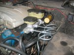
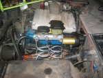
When you attach your hoses, give yourself enough clearance for the valve cover and the steering shaft. The hardest of the 3 hoses will go to the PS box. The brass fitting on the HB unit will be a return line to the PS pump. When running this line, you will have to use the brass


