Yo dfjson,
WELCOME!
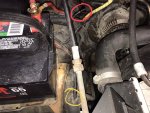
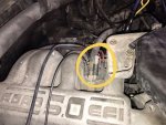
That ***** or bolt is plugging a vacuum hose from the main vacuum "tree". See info on this below.
●
For surging, try a Self Test for Diagnostic Trouble Codes (DTC)s by my pal, BroncoJoe19
Post Code(s) here according to:
KOEO & KOER
A helper can assist you by counting the codes. Some use their smart phones to record them.
BEWARE OF FAN, BELTS, PULLEYS, HOT HOSES, IGNITION HIGH TENSION WIRES, AND ENGINE COMPONENTS
Or ask local mom and dad parts stores if they will test it for you. The majority of parts chain stores tests just OBDII vehicles now.
Or purchase a coder reader such as;
"Innova ODB-1 and we generally recommend getting the extension cord with it, so you can work the ignition key in the cab while watching/holding the reader. It will save the codes but knowing when to go through the cycles and ensuring you get it right the first time can save time and hassle, especially if you're working on it by yourself, as most of us do." by BikerPepe`
Some
no code Surging usual suspects by Ford;
Vacuum leak,
see my leak diagnosis link in post #11
Air filter, is it relatively clean?
Air inlet atop radiator support to filter box and to throttle body; look for obstruction; damaged tubing, openings in tubing, loose fit at throttle body or at MAP sensor.
Fuel quality; Oxidized fuel often turns darker over time and may even smell sour. You can check stored gasoline by pouring some into a clear glass container and comparing it side-by-side with known fresh gasoline. If your old sample looks noticeably darker than the fresh gas, you have strong evidence the gas has gone bad.
Electrical connectors; inspect for corrosion, etc at coil, firewall, ICM, distributor, PCM, etc. especially those with broken locking tabs.
●
"found
one line that runs to no where and is not capped. " I assume it's circled in red. Based on its Location and its a rubber or silicone vacuum hose its attached to the top port of the Thermactor Air Bypass (TAB) Solenoid (on driver side next to ignition coil, see more info below) and goes directly to the Thermactor Air Bypass (TAB) Valve located on the passenger side near the fire wall.
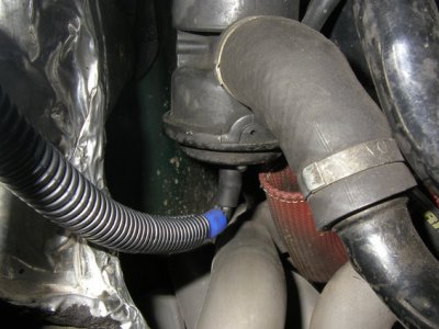
by SeattleFSB
●
The fuel rated hose that originates from under the battery and runs for about two feet is from the evaporative emission (EVAP) canister. It is a storage device for
fuel vapors that are emitted by the fuel tank in hot soak conditions. When the vehicle is at normal operating conditions the
vapors are purged from the EVAP canister. The EVAP canister is controlled by the Canister Purge Solenoid Valve (CanP/CPRV) used in EEC IV that allows the passage of the fuel vapors into the intake manifold where they are mixed with air and burned in the engine. By storing the fuel vapors and purging them into the engine at a later time hydrocarbon emissions are reduced, and fuel efficiency is increased.."
Source: by Ford motorcraftservice.com
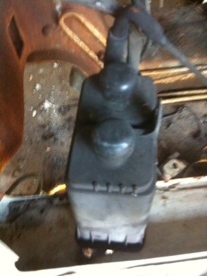
Canister Location pic in a 93 by Bbronco311
The activated charcoal inside the canister absorbs gasoline vapor from the fuel tank until the CANP (canister purge) valve opens, allowing manifold vacuum to pull fresh air in thru the dust cap(s), collecting the stored vapors, & drawing them into the engine to be burned.
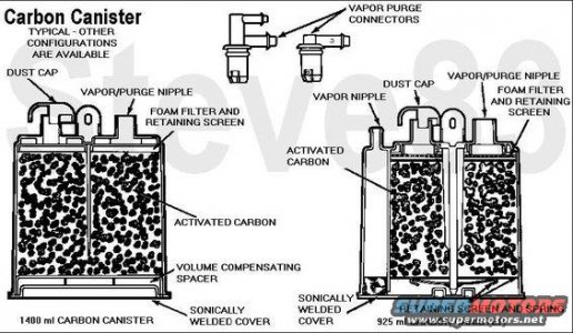
Any leak in the vacuum lines to or from the canister and CanP valve will result in dirty air entering the intake manifold, and possibly water or other contaminants.
Being virtually a zero-maintenance system, most faults are simple valve failures, hose leaks, or mechanical damage (collision, road debris, etc.).


CANP valve pics in a SeattleFSB
vapor line shown is from canister to throttle body.
●
Vacuum Tree atop intake manifold serves emissions components and vacuum tank; and to HVAC Vacuum tank.
Vacuum Line Routing Diagram for 93
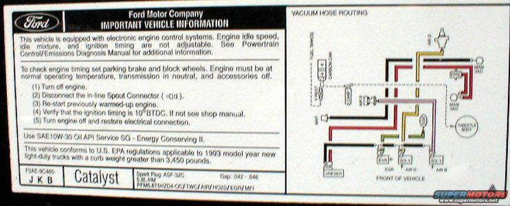
Notes:
FPRC is the Fuel Pressure Regulator on rear of driver side fuel rail described below.
VRESER is emission vacuum reservoir, aka vacuum tank, coffee can that often leaks vacuum due to rust at bottom, etc. SEE BELOW.
EGR is tge EGR Valve Position (EVP) sensor attached to the top of the EGR valve. SEE BELOW.
Both AIR B (Thermactor Air Bypass
Solenoid (TAB, AIRB, AM1))
& AIR D (Thermactor Air Diverter
Solenoid (TAD, AIRD, AM2))
are on driver side next to ignition coil
The pink and yellow hoses go to AIB B & AIR B
VALVES. See below
V REST Vapor Valve (Roll-Over) Valve on later year Depictions & Location Diagrams in 5.0, 5.8, 7.5, & 4.9; "...All fuel tank vapor valves make use of a small orifice that tends to allow only vapor and not fuel to pass into the line running forward to the vapor storage canister. This assembly mounts directly to the fuel tank using a rubber seal. Fuel vapors trapped in the sealed fuel tank are vented through the orificed vapor valve assembly in the top of the tank. The vapors leave the valve assembly through a single vapor line and continue to the carbon canister for storage, until they are purged to the engine. The vapor valve assembly mounted on the top of the fuel tank is used to control the flow of fuel vapor entering the fuel tank vapor delivery line which conducts vapor forward to the canister in normal circumstances. If due to extreme conditions, excessive pressure is generated inside the tank, the purge port opens up, allowing fuel vapor to escape to the atmosphere, and stabilizes pressure inside the tank. The valve assembly has a head valve which prevents the fuel tank from overfilling during refueling operation. The valve assembly also has a spring supported float assembly, which prevents liquid fuel from entering the vapor delivery line during severe handling, steep grades or in the event of vehicle rollover. The fuel fill cap is sealed and includes a built-in pressure-vacuum relief valve. Fuel system vacuum relief is provided after 3.5 kPa (0.50 psi) and pressure relief after 11.0 kPa (1.6 psi). Under normal operating conditions, the fill cap operates as a check valve, allowing air to enter the tank as fuel is used, while preventing vapors from escaping the tank through the cap..." by Ford via Steve
See EVR, MAP below.
View attachment 12326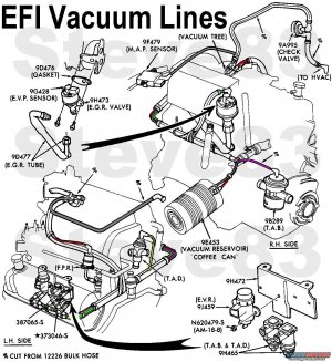
By Steve
Vacuum Line Routing Diagram, Heater/AC in a 93
/monthly_09_2012/post-3816-0-48521300-1346936396.jpg
Source: by Bronco Rob
Staying on driver side for now:
Locations in a 96, same for your 93
[
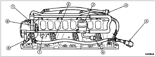
1 ECT Sensor Location sends coolant temperature to computer aka electronic engine control (EEC)
2 9F593 Fuel Injector
3 9C968 Fuel Pressure Regulator
4 9D280 Fuel Injection Supply Manifold
5 9D930 Fuel Charging Wiring
6 — Fuel Return Tube (Part of 9F792 Assembly)
7 — Intake Air Temp (IAT) Sensor
8 — Water Temperature Sender Location for temperature gauge

Pic by Shawn C
...
Intake Air Temp (IAT); (Air Charge Temperature [ACT] prior to 1992); Overview & Testing; "...This measures the temperature of the air entering the engine. Which impacts the fuel ratio; the cooler the incoming air is the denser it is. Denser air can utilize more fuel, giving us even greater accuracy in obtaining our desired air to fuel ratio. Before you start blaming the air charge temperature sensor and replacing it make sure the rest of the coolant system is in good condition. All of the following items will affect the ACT; Coolant level, Radiator Fan, Engine Temperature..." READ MORE @
http://web.archive.org/web/20101201014236/http://fordfuelinjection.com/index.php?p=29 by Ryan M
Location in an 85; "...screwed into the middle drivers side of the intake..."Source: by Chris
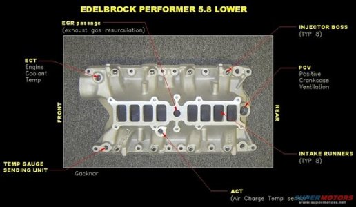 ACT,
ACT, ECT, PCV, Water Temperature Gauge Sender Location in an Edelbrock Perfomer Lower Intake Manifold Diagram
Source: by GACKNAR
92-96 IAT is located on the back side of the air filter box. (towards the fuse block)

Intake Air Temp (IAT); (Air Charge Temperature [ACT] prior to 1992)
IAT pic by Richard C
...
The engine coolant temperature sensor (ECT sensor) changes resistance in response to changing temperature of the engine coolant. The engine coolant temperature sensor resistance decreases as the engine coolant temperature increases providing a signal to the EEC.

pic by Shawn C.
..

Oil Pressure Sender for oil pressure gauge
pic by Shawn C.
...

Knock Sensor, back of engine, secondary air injection system crossover tube in background.
pic by waltman
Detects cylinder block vibrations caused by engine knock and send a signal to the computer to ****** ignition timing. FAILURE SYMPTOMS, Engine knock, loss of power, CEL.
....
Staying on driver side:
Master Cylinder & Booster Location in a 92 on firewall.

Source: by Zach K (BurnedB, BurnedBronco, Badassbronco)
...
Electronic Engine Control IV (EEC IV, aka Powertrain Control Module (PCM), COMPUTER) Location pic, accessible in engine bay, passenger side. Remove after loosening and wedging driver side plastic fender liner.
If you have Cruise control, unbolt the cruise control module from the fender for easier access. Lay it aside across the engine to get it out of the way.
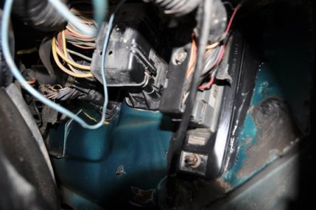
.
EEC Black Connector Bolt is shown above
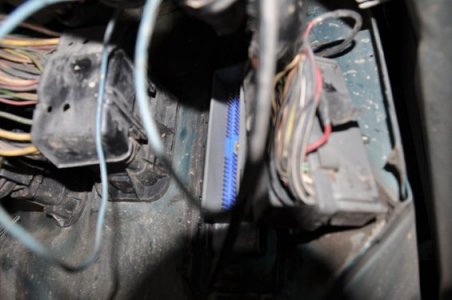
EEC MODULE IN ABOVE PIC (BLUE TERMINALS SHOWN) by bossind
Earlier years in same location, but can be removed fron drivers kick panel
Ignition Control Module (ICM) Location pics (near driver's side hood hinge); "...SPOUT connector wires come out of the ignition module wiring connector loom. Be careful when prying the tabs on both sides away to pull out the spout, they break easily. Pretty much the reason for the zip tie....the other sides missing! ..."

Source: by DNBELOWBRONCO (Kevin, Labor of Love)
...
Self Test Connectors for Diagnostic Trouble Codes (DTC)s; "They are located in the engine compartment on the driver's side just above the wheel well, (between the fire wall and the air filter box) it looks like this picture..."
/monthly_05_2008/post-9476-1209779750.jpg
by my pal, BroncoJoe19
...
Power Steering Pressure Switch (5.0); The Power Steering Pressure Switch signals the EEC IV when power steering pressure exceeds 350 psi ±50. The engine then increases idle speed to compensate for the additional load.
miesk5 note; It appears the switch was deleted from the 94 model year. It only shows up in the diagrams until 93. the switch is directly above the steering box. Your 92 may not have this switch.
...
Distributor, Idle Air Control (IAC) Valve, Schrader Valve, & Vacuum Tree (far top R)
pic

by Steve
.
Idle Air Control (IAC) Valve

by Bobby (blue)
The idle air control valve (IAC valve) is used to control engine idle speed and dashpot functions. The idle air control valve is mounted on the throttle body and allows air to bypass the throttle plate. The amount of air allowed to bypass the throttle plate, will be determined by the EEC IV and will be controlled by a duty cycle signal.
...
Ignition Coil, EGR Vacuum Regulator (EVR), TAB, TAD.

.
Ignition Coil replaced with Red MSD Coil

by SeattleFSB
Notes:
The Exhaust Gas Recirculation (EGR) System is designed to reintroduce exhaust gas into the combustion cycle lowering combustion temperatures and reducing the formation of Nitrous Oxide. The amount of exhaust gas reintroduced and the timing of the cycle varies by calibration and is controlled by factors such as engine speed, engine vacuum, exhaust system back pressure, coolant temperature and throttle angle. All EGR valves are vacuum actuated. The vacuum diagram is shown on the emission decal for each calibration.
EGR flow is controlled by the EEC through an EGR Valve Position (EVP) sensor attached to the top of the EGR valve.
The valve is operated by a vacuum signal from the EGR Vacuum Regulator (EVR) Solenoid that actuates the valve diaphragm.
As supply vacuum overcomes the spring load, the diaphragm is actuated. This lifts the pintle off its seat allowing exhaust gas to recirculate (flow). The amount of flow is proportional to the pintle position. EGR Valve Position (EVP) Sensor provides the EEC system with a signal indicating position of the EGR valve to the EEC.
The EGR valve for this system is a vacuum operated EGR valve which maintains a sonic flow in the valve seat/pintle area.
The EVP sensor and EGR valve are serviced separately.
EGR Vacuum Regulator (EVR) Solenoid; also called EGR Vacuum Solenoid, solenoid is an electromagnetic device which controls vacuum output to the EGR valve. An electric current in the coil induces a magnetic field in the armature which pulls on a disk closing the vent to atmosphere. The EEC, aka Powertrain Control Module (PCM) outputs a duty cycle to the EVR which regulates the vacuum level to the EGR valve. As the duty cycle is increased, so is the vacuum signal to the EGR valve. The vacuum source is manifold vacuum. After opening, vacuum will be directed to the EGR valve so it may open and allow gases to be recirculated into the intake manifold.
EGR Valve is required in EEC systems where EGR flow is controlled by the EEC. through an EGR Valve Position (EVP) sensor.
EGR valve for this system is a vacuum operated EGR valve which maintains a sonic flow in the valve seat/pintle area. EVP sensor (9G428 ) and EGR valve (9H473) are serviced separately.

EVP atop EGR
by waltman who points to the EGR Tube below EGR Valve, the white EVP sits atop the valve.
...

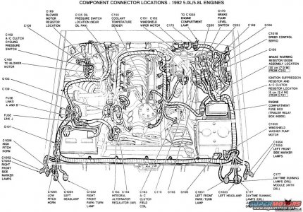
Connector C178 appears to me to be the fuel injector harness.
Diagram by Ford via Jem270
Top center front of engine, near distributor.
.
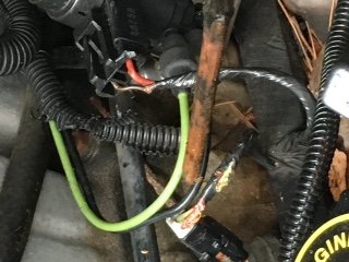
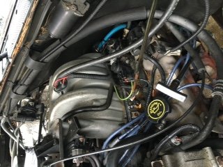
Squirrels set up a nest, chewed the harness, etc. on my 96.
...
This harness Depiction is difficult to read, but it's the only one I could locate.
.
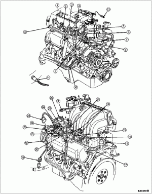
Item Part Number Description
1 — To Fuel Injector No. 4 (Part of 9D930)
2 — To Fuel Injector No. 3 (Part of 9D930)
3 — To Fuel Injector No. 2 (Part of 9D930)
4 — To Fuel Injector No. 1 (Part of 9D930)
5 — To Idle Speed Control (Part of 9D930)
6 — To EVP (Part of 9D930)
7 — To Distributor (Part of 9D930)
8 — To Engine Coolant Temperature Switch (Part of 9D930)
9 — To TPS (Part of 9D930)
10 14305 Wiring Harness to Generator
11 9F472 Heated Oxygen Sensor Assembly
12 9D930 Wiring Assembly
13 — To Radio Capacitor (reduce/eliminate Ignition noise/static in AM Band, Part of 9D930)
14 — To Tab (Part of 9D930)
15 — To Fuel Injector No. 7 (Part of 9D930)
16 — To Fuel Injector No. 8 (Part of 9D930)
17 — To Knock Sensor (Except 5.8L Engine) (Part of 9D930)
18 — To Power Steering Pressure Switch (PSPS Except 5.8L Engine) (Part of 9D930)
19 — To 12A581 Wiring Assembly (Part of 9D930)
20 — To Ignition Coil (Part of 9D930)
21 — To Intake Air Temperature Sensor (IAT, Part of 9D930)
22 — To Distributor Pigtail (Part of 9D930)
23 — To A/C Clutch (Part of 9D930)
24 — To Water Temperature Switch for temperature gauge (Part of 9D930)
25 — To Fuel Injector No. 5 (Part of 9D930)
26 — To EGR (Part of 9D930)
27 — To Fuel Injector No. 6 (Part of 9D930)
Engine Wiring, 5.0L and 5.8L Engines in a 96, similar to 92 for identification only:
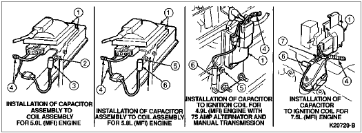
Item Part Number Description
1 12029 Coil and Bracket Assembly
2 40904-S36 *****
3 18801 Capacitor Assembly — Radio Ignition Interference Suppression
4 9D930 Wiring Assembly
5 — ***** (Part of 12029)
6 18832 Capacitor Assembly
7 — Existing Nut (Part of 12029)
Capacitor Assembly
...
Lost my reply describing components shown in this diagram by Stephen due to tablet freeze;
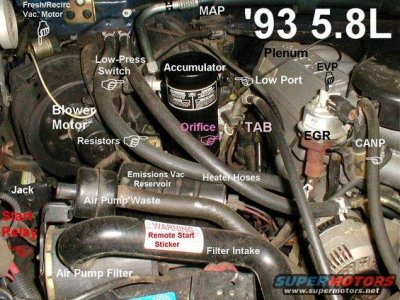
!
Will try to edit this as I save it and add more information a bit at a time.
Plenum is upper intake manifold where throttle body and some sensors are mounted. Induction System
The fuel/air mixture needed for burning in the cylinders is provided by sequential fuel injection (SFI) or multiport fuel injection (MFI in 92). Fuel is metered into the air intake stream in accordance with engine demand by eight solenoid injection valves mounted in the lower intake manifold (9424). Fuel is supplied from the vehicle's fuel tank by a high-pressure electric fuel pump (9350) mounted in the fuel tank. The fuel is filtered and sent to the fuel injection supply manifold (9F792). A fuel pressure regulator (9C968) on this fuel injection supply manifold (9D280) controls the fuel delivery pressure at a constant 269 kPa (39 psi). The eight fuel injectors are mounted above each intake runner and are connected in parallel with the fuel pressure regulator. Excess fuel supplied by the fuel pump, but not needed by the engine, is returned to the vehicle fuel tank by a fuel return line. These fuel induction systems are mounted on an intake manifold which in turn is bolted to cast iron cylinder heads.
CANP aka Canister Purge Solenoid Valve vents fuel vapors from the fuel tank to the charcoal canister, it controls the purging of these and other vapors from the fuel tank into the intake manifold when certain engine speed and temperature conditions are attained. Above idle, the mixture becomes very rich. Stumble on acceleration, poor fuel mileage, flooded charcoal canister and catalytic converter overheat can occur. Check for ruptured diaphragms inside the valve and misrouted or damaged hoses.

CANP pic, passenger side of throttle body by SeattleFSB
Alternator is shown in lower right above "Supermotors"
EGR Valve: The Exhaust Gas Recirculation (EGR) System is designed to reintroduce exhaust gas into the combustion cycle lowering combustion temperatures and reducing the formation of Nitrous Oxide. The amount of exhaust gas reintroduced and the timing of the cycle varies by calibration and is controlled by factors such as engine speed, engine vacuum, exhaust system back pressure, coolant temperature and throttle angle. All EGR valves are vacuum actuated. The vacuum diagram is shown on the emission decal for each calibration. Did you check with dealer for this VECI label?

EGR & EVP pic by SeattleFSB
Below the EGR is its Tube aka EGR Tube, attached to EGR valve & ends @ lower intake manifold port.
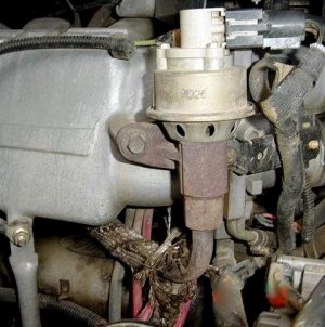
pic by Ryan M in a 5.0
"....you can see the other end of the egr pipe going into the center of the intake..." by Waltman


Starter Relay, to extreme left is a relay switch is an electrically operated switch used to connect the windings in the starter motor solenoid to the battery. The relay consists of a coil, plunger and contact disc. When the coil is connected to battery power through the ignition switch, it becomes an electromagnet. The magnetic force draws the plunger into the coil core. A disc connected to the plunger contacts the relay terminal, completing the battery to solenoid circuit. When the key or button is released, the magnetic field in the coil collapses and spring pressure returns the plunger and contact disc to the open circuit position.

Relay pic in a 90 by ElKabong (Ken, El Kabong)
Air Pump Filter, Filter Intake, Air Pump Waste is for the Secondary Air Injection; Pump (Smog Pump) that pumps fresh air into the exhaust system, to burn left over hydrocarbons, lowering emissions. The EEC IV uses 2 air valves (TAB & TAD) to control where the air flows depending on engine operation. Thermactor Air Bypass (TAB) shunts air to the atmosphere, when no air is needed. When air is needed it sends air to the second valve TAD. Thermactor Air Diverter (TAD) diverts air either to the exhaust manifold, or directly to catalytic converter..."

Emissions Vac Reservoir aka VRESER or coffee can stores vacuum and provides "muscle" vacuum. It prevents rapid fluctuations or sudden drops in a vacuum signal such as those seen during an acceleration period. When charged initially with 51-67 kPa (15-20 in-Hg) vacuum, vacuum loss shall not exceed 2 kPa (.5 in-Hg) in 60 seconds. If it does, replace the reservoir due to rust.

pic by SeattleFSB
Resistors Blower Motor Control. Three of four operating speeds (LOW, MEDIUM LOW and MEDIUM HIGH) are controlled by a heater blower motor switch resistor connected in series with three of the operating positions and the ground. The MEDIUM LOW and MEDIUM HIGH positions on the heater control are identified by dots on the control.
With the heater blower motor switch in its LOW position, current flow in the ground circuit passes through three of the coils in the heater blower motor switch resistor. In MEDIUM LOW, current flows through two coils. In MEDIUM HIGH, current flows through one coil. In HIGH, current flow in the motor ground circuit bypasses the heater blower motor switch resistor to provide maximum speed. They often become packed with leaf debris, as does the blower motor.
Blower Motor is housed in the A/C blower housing) inside the engine compartment. Blower speed is controlled by the heater blower motor switch located on the heater control on the instrument panel to the right of the steering column. A blower motor wheel is attached to the blower motor. The blower motor and blower motor wheel control the volume of air delivered to the passenger compartment, which is determined through blower motor speed selection
Low Pressure Switch is located on the accumulator. This is also called the receiver/dryer. It is a cylinder, black or aluminum, mounted just ahead of the evaporator/blower assembly. The switch is threaded onto a port on the side of the accumulator. Here is a tiny photo of the general area you will be looking at;
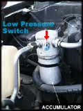
There should be a two wire plug attached to the switch. Unplug the connector, use a jumper wire to short the two pins together. Start the truck, turn on the A/C, verify if the clutch engages. If it does, then it a bad switch or extremely low charge of refrigerant that is causing your problem. The low pressure/clutch cycling switch is closed between ~24 and 45 PSI.If it does not work then it is another electrical problem further upstream. Your A/C should also have a high pressure switch. It should be attached to the line between the compressor and condenser, that would also prevent the clutch from engaging. The high pressure switch is supposed to open at ~400PSI. by rla2005 (Randy)
Accumulator aka suction accumulator/drier is mounted to the front side of the A/C evaporator case and attaches directly to the outlet tube. Refrigerant enters the accumulator/drier canister through the inlet tube and the heavier, oil-laden refrigerant falls to the bottom of the canister. A small diameter aspirator tube is located close to the bottom of the canister and runs to the top of the vapor return tube. This aspirator tube is covered with a filter screen and allows a small amount of the heavier liquid refrigerant and oil mixture to re-enter the A/C manifold and tube at a controlled rate. When the heavier liquid refrigerant and oil mixture enters the compressor evaporator to compressor suction line (19867), it has a second opportunity to vaporize and circulate through the A/C compressor without causing damage to the A/C compressor due to refrigerant slugging. A desiccant bag is mounted inside the suction accumulator/drier canister to absorb any moisture that may be in the refrigerant system. A fitting located on the side of the canister is used to attach the A/C cycling switch. A long-travel Schrader valve stem core is installed in the fitting opening to prevent refrigerant loss when the A/C cycling switch is removed.
Low Port aka Low Pressure Port; & High Pressure Port Location in a 93; "...The port on the left (passenger side), located on the accumulator, is the low side.
http://s694.photobucket.com/user/dencaw/media/newbroncoacphoto1.jpg.html
pic by Bill
"The one on the right (driver side), on the line leading to the condenser, is the high side. You very well may be throwing money away by trying to charge the system without checking for why it is empty in the first place. It's a crap shoot whether it will hold a charge for any length of time or not..." by rla2005 (Randy)
Orifice aka A/C Evaporator Core Orifice. The inlet tube to the A/C evaporator core is fitted with an A/C evaporator core orifice to control refrigerant flow. This A/C evaporator core orifice can be removed from the inlet tube and A/C evaporator core for replacement if it becomes necessary. However, Fixed Orifice Tube Tool D80L-19990-A or equivalent is necessary to prevent breakage when removing the A/C evaporator core orifice. The A/C evaporator core orifice is a restriction between the high and low pressure refrigerant and meters the flow of liquid refrigerant into the A/C evaporator core. The diameter of the orifice within the A/C evaporator core orifice is 1.575mm (0.062 inch). The A/C evaporator core orifice can be identified by the RED body color and white outlet tip.
The A/C evaporator core orifice is located in the evaporator core inlet tube and has filter screens on the inlet and outlet ends of the body. The filter screens act as strainers for the liquid refrigerant flowing through the opening. O-rings on the A/C evaporator core orifice prevent the high pressure liquid refrigerant from bypassing the A/C evaporator core orifice. Adjustment or repairs cannot be made to the A/C evaporator core orifice and it must be replaced as a unit.
Fresh/Outside Recerc Vac Motor is the Recirculation/Fresh Air Control vacuum "motor" & vac line as shown in this
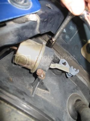
pic by John D.
The vehicle heating system draws outside air into it and distributes this fresh air throughout the passenger compartment in all positions except OFF. If the vehicle is equipped with air conditioning, outside air is distributed throughout the vehicle in all positions except OFF and MAX A/C. In these positions (OFF, MAX A/C) the A/C fresh air inlet door is in the closed position and air within the passenger compartment is recirculated throughout.
MAP aka Manifold Absolute Pressure Sensor operates as a piezoelectric (pressure-sensing) disc. However, rather than generating a voltage, its output is a frequency change. The sensor changes frequency relative to intake manifold vacuum. The sensor frequency increases as vacuum increases. The MAP sensor allows the EEC IV to determine what the engine load is. Its signal affects air/fuel ratio, ignition timing, EGR flow and altitude compensation.

MAP pic (circled) by Jem270
Some stragglers:
Throttle body is the part of the air intake system that controls the amount of air flowing into the engine, in response to driver accelerator pedal input in the main. The largest piece inside the throttle body is the throttle plate, which is a butterfly valve that regulates the airflow. The accelerator pedal motion is communicated via the throttle cable, to activate the throttle linkages, which move the throttle plate.

Throttle Body with its black plastic cover atop intake manifold

Without cover
pics by Xris
Throttle Position Sensor (TPS) monitors the throttle opening for the EEC IV to adjust fuel flow. FAILURE SYMPTOMS, Hesitation, tip in surge, engine pinging,no torque converter lock-up. "Check Engine" light on. Inspect for proper operation and adjust voltages when necessary. Check for corrosion on connectors

pic by Xris
