Accelerator Pedal
SECTION 310-02: Acceleration Control
2008 Crown Victoria/Grand Marquis Workshop Manual
REMOVAL AND INSTALLATION
Procedure revision date: 02/11/2008
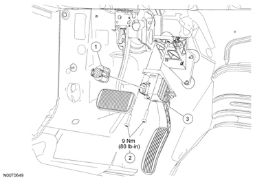
Accelerator Pedal
Removal and Installation

Item
Part Number
Description
1
14A464
Accelerator pedal sensor electrical connector
2
W506015
Accelerator pedal bolts (2 required)
3
9N972
Accelerator pedal
Acceleration Control; The acceleration controls consist of the accelerator pedal and sensor assembly. The engine management system electronically operates the throttle of the engine in response to accelerator pedal movements initiated by the driver. In the event of a system failure, the engine management system provides a "limp home" mode whichallows the car to be driven with limited performance.
ANY CODES?
No Diagnostic Trouble Codes (DTCs) Present Symptom Chart Index
NO CODES System/Symptom
Oasis Number
Chart Number
Stalls/Quits
Idle/Acceleration/Cruise
607x00
Chart Number: 1
Deceleration
607700
Chart Number: 6
Stall after start
607000
Chart Number: 1
Runs Rough
608x00
Chart Number: 1
Misses
609x00
Chart Number: 1
Buck/****
610x00
Chart Number: 1
Hesitation/Stumble
611x00
Chart Number: 1
 Surge
Surge
612x00
Chart Number: 1
Backfires
613x00
Chart Number: 7

 Lack/Loss of Power
614x00
Chart Number: 8
Spark Knock
615x00
Chart Number: 9
NOTE
Note: OASIS identifiers (the x means any number (1-9) can be used) xxx4xx equals during idle, xxx5xx equals during acceleration, xxx6xx equals during cruise, xxx7xx equals during deceleration.
Charts
2008 PCED Gasoline Engines
SECTION 3: Symptom Charts
Procedure revision date: 12/20/2011
No Diagnostic Trouble Codes (DTCs) Present Symptom Charts
Chart 1
NOTE
Note: For some vehicle applications, the engine may stall if left running while refueling. Advise the customer to turn the engine off while refueling to avoid contamination or damage to the evaporative emission (EVAP) system.
SYSTEM/COMPONENT
REFERENCE (Section 5 Pinpoint Test unless noted)
Chart 8
NOTE
Note: Verify the symptom is reported under normal driving conditions without excessive engine or vehicle load. Also, be aware of the engine RPM/speed limiting functions of the PCM.
NOTE
Note: For vehicles equipped with a knock sensor, a lack of power may result when the vehicle is operated with a breakout box installed at the PCM. The knock sensor circuits are not shielded in the breakout box, and knock sensor signal noise may be noticed by the PCM. If this happens, spark timing is ******** and a lack of power may result.
NOTE
Note: For applications with a knock sensor, a lack of power may result if the engine has developed an abnormal noise. The knock sensors may interpret some abnormal noise as detonation and ****** spark timing.
SYSTEM/COMPONENT
REFERENCE (Section 5 Pinpoint Test unless noted)
Additional Driveability Concerns
DK: Accelerator Pedal Position (APP) Sensor:
Note: After clearing an APP sensor diagnostic trouble code (DTC) to verify a repair or an intermittent concern, apply the accelerator pedal before carrying out the self-test. Take 10 seconds to carry out a full sweep of the accelerator pedal from fully released to fully applied and back to fully released.
This pinpoint test is intended to diagnose the following:
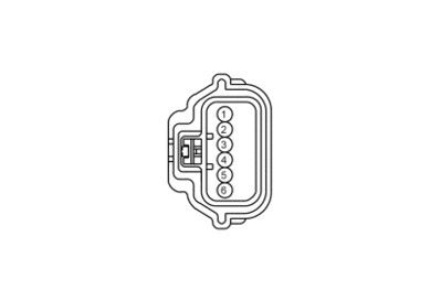
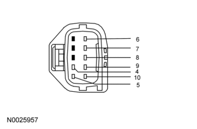
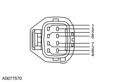
Accelerator Pedal Position (APP) Sensor Connector
A

Click to Enlarge
B

Click to Enlarge
C

Click to Enlarge
Vehicle
Connector
Pin
Circuit
Focus
A
5
2
3, 4
1, 6
APP2
APP1
ETCRTN
ETCREF
Fusion,
Milan,
MKZ
B
4
5
7
6, 9
10, 8
APP3
APP2
APP1
ETCRTN
ETCREF
All other vehicles
C
8
5
2
1, 3
6, 7
APP3
APP2
APP1
ETCRTN
ETCREF
Powertrain Control Module (PCM) Connector
For PCM connector views or reference values, refer to Reference Values.
Vehicle
Connector
Pin
Circuit
Crown Victoria,
Grand Marquis,
Mustang,
Town Car
170 Pin
B41, B6, E59
B24, B4, E66
B35, B36
B28
B17
B5
ETCRTN
ETCREF
VPWR
APP3
APP2
APP1
E-Series,
F-Super Duty
170 Pin
B18, B6, E59
B16, B4, E66
B35, B36
B28
B17
B5
ETCRTN
ETCREF
VPWR
APP3
APP2
APP1
Expedition,
Navigator
140 Pin
B59, B65, E59
B21, B28, E66
B51, B52, B53
B27
B26
B25
ETCRTN
ETCREF
VPWR
APP3
APP2
APP1
Explorer,
Explorer Sport Trac,
Mountaineer
170 Pin
B43, B6, E59
B24, B4, E66
B35, B36
B28
B17
B5
ETCRTN
ETCREF
VPWR
APP3
APP2
APP1
F-150,
Mark LT
190 Pin
B58, B59, E59
B21, B28, E66
B51, B52, B53
B27
B26
B25
ETCRTN
ETCREF
VPWR
APP3
APP2
APP1
Focus
190 Pin
B44, B60, E60
B45, B61, E59
B67, B68
B29
B28
ETCRTN
ETCREF
VPWR
APP2
APP1
Fusion,
Milan,
MKZ
140 Pin
B59, B60, E59
B21, B28, E66
B51, B52
B27
B26
B25
ETCRTN
ETCREF
VPWR
APP3
APP2
APP1
All other vehicles
190 Pin
B59, B65, E59
B21, B28, E66
B51, B52, B53
B27
B26
B25
ETCRTN
ETCREF
VPWR
APP3
APP2
APP1
DK1 CHECK FOR DIAGNOSTIC TROUBLE CODES (DTCS)
Are DTCs P1575, P2104, P2121, P2122, P2123, P2126, P2127, P2128, P2131, P2132, P2133, or P2138 present?
Yes
No
For DTC P1575, GO to DK2.
For all others, GO to DK4.
For a lack/loss of power, GO to DK3.
For all others, GO to Section 4, Diagnostic Trouble Code (DTC) Charts and Descriptions.
DK2 DTC P1575: REPEAT THE KOEO SELF-TEST
Yes
No
DISREGARD the current diagnostic trouble code (DTC) at this time. DIAGNOSE the next DTC. GO to Section 4, Diagnostic Trouble Code (DTC) Charts and Descriptions.
GO to DK3.
DK3 CHECK THE ACCELERATOR PEDAL FOR OBSTRUCTION
Yes
No
GO to DK4.
ISOLATE and REPAIR the obstruction.
CLEAR the DTCs. REPEAT the self-test.
DK4 CHECK THE APP SENSOR SIGNAL VOLTAGE RANGES FOR THE ACCELERATOR PEDAL FULLY APPLIED AND RELEASED POSITIONS
Yes
No
GO to DK5.
For continuous memory DTCs P2121 and P2126 with P2131, GO to DK24.
For all others, GO to DK5.
DK5 CHECK THE VREF VOLTAGE TO APP SENSOR
Yes
No
For E-Series, Explorer, Explorer Sport Trac, F-150, Mark LT, and Mountaineer, GO to DK6.
For F-Super Duty, GO to DK7.
For Fusion, Milan, and MKZ, GO to DK10.
For Focus with DTC P2122, P2123, or P2138, GO to DK12.
For Focus with DTC P2127 or P2128, GO to DK16.
For all others, GO to DK11.
GO to Pinpoint Test C.
DK6 E-SERIES, EXPLORER, EXPLOREReen:
Yes
No
For DTCs P2121, P2122 or P2123 alone or in combination, GO to DK12.
For DTCs P2126, P2127 or P2128 alone or in combination, GO to DK16.
For DTCs P2131, P2132 or P2133 alone or in combination, GO to DK20.
For DTC P2104 alone, GO to DK30.
For a lack/loss of power, the concern is elsewhere. RETURN to Symptom Charts, Symptom Charts for further direction.
For all others, GO to DK24.
INSTALL a new APP sensor. REFER to the Workshop Manual Section 310-02, Acceleration Control to INSTALL a new accelerator pedal.
CLEAR the DTCs. REPEAT the self-test.
●●● Joe, I'll stop here for now in this test.
System/Symptom
Oasis Number
Chart Number
Stalls/Quits
Idle/Acceleration/Cruise
607x00
Chart Number: 1
Deceleration
607700
Chart Number: 6
Stall after start
607000
Chart Number: 1
Runs Rough
608x00
Chart Number: 1
Misses
609x00
Chart Number: 1
Buck/****
610x00
Chart Number: 1
Hesitation/Stumble
611x00
Chart Number: 1
Surge
612x00
Chart Number: 1
Backfires
613x00
Chart Number: 7
Lack/Loss of Power
614x00
Chart Number: 8
Spark Knock
615x00
Chart Number: 9
NOTE
Note: OASIS identifiers (the x means any number (1-9) can be used) xxx4xx equals during idle, xxx5xx equals during acceleration, xxx6xx equals during cruise, xxx7xx equals during deceleration.
SECTION 310-02: Acceleration Control
2008 Crown Victoria/Grand Marquis Workshop Manual
REMOVAL AND INSTALLATION
Procedure revision date: 02/11/2008
Accelerator Pedal
Removal and Installation

Item
Part Number
Description
1
14A464
Accelerator pedal sensor electrical connector
2
W506015
Accelerator pedal bolts (2 required)
3
9N972
Accelerator pedal


NOTE
NOTE: To prevent setting DTCs, make sure the ignition switch is in the OFF position prior to disconnecting the accelerator pedal sensor electrical connectors.
Disconnect the accelerator pedal sensor electrical connector.
- Remove the 2 bolts and the accelerator pedal assembly.
To install, tighten to 9 Nm (80 lb-in).
- To install, reverse the removal procedure
Acceleration Control; The acceleration controls consist of the accelerator pedal and sensor assembly. The engine management system electronically operates the throttle of the engine in response to accelerator pedal movements initiated by the driver. In the event of a system failure, the engine management system provides a "limp home" mode whichallows the car to be driven with limited performance.
ANY CODES?
No Diagnostic Trouble Codes (DTCs) Present Symptom Chart Index
NO CODES System/Symptom
Oasis Number
Chart Number
Stalls/Quits
Idle/Acceleration/Cruise
607x00
Chart Number: 1
Deceleration
607700
Chart Number: 6
Stall after start
607000
Chart Number: 1
Runs Rough
608x00
Chart Number: 1
Misses
609x00
Chart Number: 1
Buck/****
610x00
Chart Number: 1
Hesitation/Stumble
611x00
Chart Number: 1
612x00
Chart Number: 1
Backfires
613x00
Chart Number: 7
614x00
Chart Number: 8
Spark Knock
615x00
Chart Number: 9
NOTE
Note: OASIS identifiers (the x means any number (1-9) can be used) xxx4xx equals during idle, xxx5xx equals during acceleration, xxx6xx equals during cruise, xxx7xx equals during deceleration.
Charts
2008 PCED Gasoline Engines
SECTION 3: Symptom Charts
Procedure revision date: 12/20/2011
No Diagnostic Trouble Codes (DTCs) Present Symptom Charts
Chart 1
- Stalls/Quits: Idle, Acceleration, Cruise, Stall After Start
- Runs Rough
- Misses
- Buck/****
- Hesitation/Stumble
 Surge
Surge
- Unique Idle Concerns: Rolling Idle
NOTE
Note: For some vehicle applications, the engine may stall if left running while refueling. Advise the customer to turn the engine off while refueling to avoid contamination or damage to the evaporative emission (EVAP) system.
SYSTEM/COMPONENT
REFERENCE (Section 5 Pinpoint Test unless noted)
- Check the following parameter identifiers (PIDs):
- DPFEGR (if equipped) (hot idle value within 0.15 volt of the key ON, engine OFF value)
- LONGFT1/LONGFT2 (value between -20 and +20%)
- VPWR (value between 10.5 and 17.0 volts, and within 0.5 volt of battery voltage)
- DPFEGR PID value not within 0.15 volt of key ON, engine OFF value:
- For vehicles equipped with an exhaust gas recirculation system module (ESM), GO to Pinpoint Test HH.
- For all others, GO to Pinpoint Test HE.
- LONGFT1/LONGFT2 value low (-):
- Continue diagnosis. Concentrate checks in areas that would cause the engine to run rich.
- LONGFT1/LONGFT2 value high (+):
- Continue diagnosis. Concentrate checks in areas that would cause the engine to run lean.
- VPWR not between 10.5 and 17.0 volts:
- REFER to the Workshop Manual Section 414-00, Charging System and carry out the Inspection and Verification to continue diagnosis.
- VPWR between 10.5 and 17.0 volts, but not within 0.5 volt of battery voltage:
- CHECK the B+ voltage to the powertrain control module (PCM) power relay. CHECK the VPWR circuit between the PCM and the PCM power relay. CHECK the PWR GND circuits.
- For vehicles that run rough at idle:
- Check the INJx_F PIDs (the "x" indicates the injector number) with the key ON, engine running. There is 1 INJx_F PID for each engine cylinder. All INJx_F PIDs must indicate no fault (or NO).
- The INJx_F PID(s) indicate a fault (an injector circuit concern is indicated), GO to Pinpoint Test KG.
- Mass Air Flow (MAF) Sensor
- GO to Pinpoint Test DC.
- Secondary Ignition System
- For vehicles equipped with a coil pack ignition system, GO to Pinpoint Test JC.
- For all others, GO to Pinpoint Test JB.
- Fuel Delivery System
- GO to Pinpoint Test HC.
- Exhaust System
- GO to Pinpoint Test HF.
- Positive Crankcase Ventilation (PCV) System
- GO to Pinpoint Test HG.
- EVAP System
- GO to Pinpoint Test HX.
- Charging System
- GO to Pinpoint Test HY.
- Heated Oxygen Sensor (HO2S) (for Taurus, Taurus X, Sable PZEVs)
- GO to Pinpoint Test DZ.
- Automatic Transmission
- REFER to the Workshop Manual Section 307-01, Automatic Transmission/Transaxle diagnostic strategy to continue diagnosis.
- Base Engine
- REFER to the Workshop Manual Section 303-00, Engine System and carry out the Inspection and Verification to continue diagnosis.
- Intake Air System
- GO to Pinpoint Test HU.
- A/C Pressure (ACP) Transducer Sensor
- GO to Pinpoint Test DS.
- Additional Testing
- GO to Pinpoint Test Z.
- Additional Checks:
- Some vehicles have a TQ_CNTRL PID available. Check this PID to determine if the PCM is reducing torque, and if so, why the torque is being reduced. As a PID display example; 0 equals no torque reduction requested, 1 equals torque truncation, which cuts fuel to protect when line pressure falls to minimum limit and 2 equals traction control event, which cuts fuel/spark for traction control.
- Correct PCM vehicle identification (VID) block information. Refer to Section 2, Flash Electrically Erasable Programmable Read Only Memory (EEPROM) to carry out the Making Changes to the VID Block procedure.
- Be aware of engine RPM/speed limiting functions of the PCM (look for incorrect high vehicle speed signal from ABS, VSS, or OSS).
- Drivelines
- Manual transmission/clutch
- Charging system
- Traction control system (if equipped)
- A/C system (for surge with A/C on)
- Speed control system (for surge with speed control on)
- A/C compressor diode, if equipped (for rolling idle)
- REFER to the applicable Workshop Manual section.
Chart 8
- Lack/Loss of Power
NOTE
Note: Verify the symptom is reported under normal driving conditions without excessive engine or vehicle load. Also, be aware of the engine RPM/speed limiting functions of the PCM.
NOTE
Note: For vehicles equipped with a knock sensor, a lack of power may result when the vehicle is operated with a breakout box installed at the PCM. The knock sensor circuits are not shielded in the breakout box, and knock sensor signal noise may be noticed by the PCM. If this happens, spark timing is ******** and a lack of power may result.
NOTE
Note: For applications with a knock sensor, a lack of power may result if the engine has developed an abnormal noise. The knock sensors may interpret some abnormal noise as detonation and ****** spark timing.
SYSTEM/COMPONENT
REFERENCE (Section 5 Pinpoint Test unless noted)
- Automatic Transmission Fluid
- Visual
- Throttle Linkage
- Visual
- Air Cleaner Element
- Visual
- Check the following PIDS:
- LONGFT1/LONGFT2 (value between -20 and +20%)
- IMTVF (if equipped): For both key ON, engine OFF and key ON, engine running with the transmission in PARK/NEUTRAL and the engine RPM greater than 3,000 RPM, the PID should indicate no fault (or NO) in both situations.
- LONGFT1/LONGFT2 value low (-):
- Continue diagnosis. Concentrate checks in areas that would cause the engine to run rich.
- LONGFT1/LONGFT2 value high (+):
- Continue diagnosis. Concentrate checks in areas that would cause the engine to run lean.
- IMTVF PID indicates a fault:
- GO to Pinpoint Test HU.
- Fuel Delivery System
- GO to Pinpoint Test HC.
- Secondary Ignition
- For vehicles equipped with a coil pack ignition system, GO to Pinpoint Test JC.
- For all others, GO to Pinpoint Test JB.
- MAF Sensor
- GO to Pinpoint Test DC.
- Exhaust System
- GO to Pinpoint Test HF.
- Variable Camshaft Timing (VCT) System
- GO to Pinpoint Test HK.
- Accelerator Pedal Position Sensor
- GO to Pinpoint Test DK.
- Base Engine
- REFER to the Workshop Manual Section 303-00, Engine System and carry out the Inspection and Verification to continue diagnosis.
- Automatic Transmission
- REFER to the Workshop Manual Section 307-01, Automatic Transmission/Transaxle diagnostic strategy to continue diagnosis.
- Brake System Drag or Binding
- REFER to the Workshop Manual Section 206-00, Brake System.
- Supercharger Bypass System
- GO to Pinpoint Test KJ.
- Additional Testing
- GO to Pinpoint Test Z.
- Additional Checks:
- Some vehicles have a TQ_CNTRL PID available. Check this PID to determine if the PCM is reducing torque, and if so, why the torque is being reduced. As a PID display example; 0 equals no torque reduction requested, 1 equals torque truncation, which cuts fuel to protect when line pressure falls to minimum limit, and 2 equals traction control event, which cuts fuel/spark for traction control.
- Customer driving habits
- Correct PCM vehicle identification (VID) block information. Refer to Section 2, Flash Electrically Erasable Programmable Read Only Memory (EEPROM) to carry out the Making Changes to the VID Block procedure.
- Intake manifold runner control (IMRC) linkage (if equipped)
- Clutch (M/T)
- Charging system
- Engine RPM/speed limiting functions of the PCM (look for incorrect high vehicle speed signal from ABS, VSS, or OSS)
- Visual. REFER to the applicable Workshop Manual section.
Additional Driveability Concerns
DK: Accelerator Pedal Position (APP) Sensor:
Note: After clearing an APP sensor diagnostic trouble code (DTC) to verify a repair or an intermittent concern, apply the accelerator pedal before carrying out the self-test. Take 10 seconds to carry out a full sweep of the accelerator pedal from fully released to fully applied and back to fully released.
This pinpoint test is intended to diagnose the following:
- accelerator pedal position (APP) sensor (9F836)
- harness circuits: ETCRTN, SIGRTN, ETCREF, APP1, APP2, and APP3
- powertrain control module (PCM) (12A650)
Accelerator Pedal Position (APP) Sensor Connector
A

Click to Enlarge
B

Click to Enlarge
C

Click to Enlarge
Vehicle
Connector
Pin
Circuit
Focus
A
5
2
3, 4
1, 6
APP2
APP1
ETCRTN
ETCREF
Fusion,
Milan,
MKZ
B
4
5
7
6, 9
10, 8
APP3
APP2
APP1
ETCRTN
ETCREF
All other vehicles
C
8
5
2
1, 3
6, 7
APP3
APP2
APP1
ETCRTN
ETCREF
Powertrain Control Module (PCM) Connector
For PCM connector views or reference values, refer to Reference Values.
Vehicle
Connector
Pin
Circuit
Crown Victoria,
Grand Marquis,
Mustang,
Town Car
170 Pin
B41, B6, E59
B24, B4, E66
B35, B36
B28
B17
B5
ETCRTN
ETCREF
VPWR
APP3
APP2
APP1
E-Series,
F-Super Duty
170 Pin
B18, B6, E59
B16, B4, E66
B35, B36
B28
B17
B5
ETCRTN
ETCREF
VPWR
APP3
APP2
APP1
Expedition,
Navigator
140 Pin
B59, B65, E59
B21, B28, E66
B51, B52, B53
B27
B26
B25
ETCRTN
ETCREF
VPWR
APP3
APP2
APP1
Explorer,
Explorer Sport Trac,
Mountaineer
170 Pin
B43, B6, E59
B24, B4, E66
B35, B36
B28
B17
B5
ETCRTN
ETCREF
VPWR
APP3
APP2
APP1
F-150,
Mark LT
190 Pin
B58, B59, E59
B21, B28, E66
B51, B52, B53
B27
B26
B25
ETCRTN
ETCREF
VPWR
APP3
APP2
APP1
Focus
190 Pin
B44, B60, E60
B45, B61, E59
B67, B68
B29
B28
ETCRTN
ETCREF
VPWR
APP2
APP1
Fusion,
Milan,
MKZ
140 Pin
B59, B60, E59
B21, B28, E66
B51, B52
B27
B26
B25
ETCRTN
ETCREF
VPWR
APP3
APP2
APP1
All other vehicles
190 Pin
B59, B65, E59
B21, B28, E66
B51, B52, B53
B27
B26
B25
ETCRTN
ETCREF
VPWR
APP3
APP2
APP1
DK1 CHECK FOR DIAGNOSTIC TROUBLE CODES (DTCS)
Are DTCs P1575, P2104, P2121, P2122, P2123, P2126, P2127, P2128, P2131, P2132, P2133, or P2138 present?
Yes
No
For DTC P1575, GO to DK2.
For all others, GO to DK4.
For a lack/loss of power, GO to DK3.
For all others, GO to Section 4, Diagnostic Trouble Code (DTC) Charts and Descriptions.
DK2 DTC P1575: REPEAT THE KOEO SELF-TEST
- Key ON, engine OFF.
- Carry out the KOEO self-test.
Yes
No
DISREGARD the current diagnostic trouble code (DTC) at this time. DIAGNOSE the next DTC. GO to Section 4, Diagnostic Trouble Code (DTC) Charts and Descriptions.
GO to DK3.
DK3 CHECK THE ACCELERATOR PEDAL FOR OBSTRUCTION
- Key ON, engine OFF.
- Press the accelerator pedal fully to the floor and release.
Yes
No
GO to DK4.
ISOLATE and REPAIR the obstruction.
CLEAR the DTCs. REPEAT the self-test.
DK4 CHECK THE APP SENSOR SIGNAL VOLTAGE RANGES FOR THE ACCELERATOR PEDAL FULLY APPLIED AND RELEASED POSITIONS
- Access the PCM and monitor the APP1, APP2 and APP3 PIDs.
- Press the accelerator pedal fully to the floor and release.
Vehicle
APP1
APP2
APP3
E-Series
0.73 - 1.28
3.03 - 4.55
2.59 - 3.89
Expedition, Navigator
0.79 - 2.09
2.75 - 4.33
2.26 - 3.73
Explorer, Explorer Sport Trac, Mountaineer
0.60 - 1.57
3.07 - 4.50
2.57 - 3.89
F-150, Mark LT
0.60 - 1.57
3.07 - 4.50
2.57 - 3.89
F-Super Duty
0.28 - 0.97
3.45 - 4.71
2.95 - 4.10
Focus
3.69 - 4.60
1.75 - 2.40
-
Fusion, Milan, MKZ
1.20 - 2.50
2.50 - 3.94
2.00 - 3.33
All others
0.48 - 1.76
2.95 - 4.62
2.43 - 4.02
Vehicle
APP1
APP2
APP3
Focus
0.70 - 0.90
0.30 - 0.50
-
All vehicles
3.43 - 4.69
1.13 - 1.88
0.64 - 1.28
- Accelerator Pedal Fully Applied Voltage ValuesAccelerator Pedal Fully Released Voltage Values
Yes
No
GO to DK5.
For continuous memory DTCs P2121 and P2126 with P2131, GO to DK24.
For all others, GO to DK5.
DK5 CHECK THE VREF VOLTAGE TO APP SENSOR
- Key in OFF position.
- APP Sensor connector disconnected.
- Key ON, engine OFF.
- Measure the voltage between:
( + ) APP Sensor Connector, Harness Side
( - ) APP Sensor Connector, Harness Side
ETCREF
ETCRTN
Yes
No
For E-Series, Explorer, Explorer Sport Trac, F-150, Mark LT, and Mountaineer, GO to DK6.
For F-Super Duty, GO to DK7.
For Fusion, Milan, and MKZ, GO to DK10.
For Focus with DTC P2122, P2123, or P2138, GO to DK12.
For Focus with DTC P2127 or P2128, GO to DK16.
For all others, GO to DK11.
GO to Pinpoint Test C.
DK6 E-SERIES, EXPLORER, EXPLOREReen:
(+) APP Sensor Connector, Component Side
(-) APP Sensor Connector, Component Side
Minimum Resistance (ohms)
Maximum Resistance (ohms)
APP1
ETCREF
550
1,390
APP1
ETCRTN
1,030
2,590
APP1
APP2
2,125
5,335
APP1
APP3
1,930
4,845
APP2
ETCREF
1,785
4,480
APP2
ETCRTN
1,475
3,705
APP2
APP3
2,520
6,330
APP3
ETCREF
1,620
4,070
APP3
ETCRTN
1,135
2,860
ETCREF
ETCRTN
780
1,955
ETCREF
ETCREF
0
10
ETCRTN
ETCRTN
0
10
Yes
No
For DTCs P2121, P2122 or P2123 alone or in combination, GO to DK12.
For DTCs P2126, P2127 or P2128 alone or in combination, GO to DK16.
For DTCs P2131, P2132 or P2133 alone or in combination, GO to DK20.
For DTC P2104 alone, GO to DK30.
For a lack/loss of power, the concern is elsewhere. RETURN to Symptom Charts, Symptom Charts for further direction.
For all others, GO to DK24.
INSTALL a new APP sensor. REFER to the Workshop Manual Section 310-02, Acceleration Control to INSTALL a new accelerator pedal.
CLEAR the DTCs. REPEAT the self-test.
●●● Joe, I'll stop here for now in this test.
System/Symptom
Oasis Number
Chart Number
Stalls/Quits
Idle/Acceleration/Cruise
607x00
Chart Number: 1
Deceleration
607700
Chart Number: 6
Stall after start
607000
Chart Number: 1
Runs Rough
608x00
Chart Number: 1
Misses
609x00
Chart Number: 1
Buck/****
610x00
Chart Number: 1
Hesitation/Stumble
611x00
Chart Number: 1
Surge
612x00
Chart Number: 1
Backfires
613x00
Chart Number: 7
Lack/Loss of Power
614x00
Chart Number: 8
Spark Knock
615x00
Chart Number: 9
NOTE
Note: OASIS identifiers (the x means any number (1-9) can be used) xxx4xx equals during idle, xxx5xx equals during acceleration, xxx6xx equals during cruise, xxx7xx equals during deceleration.
Last edited by a moderator:
