Yo one,
Welcome!
DTC 18 - IDM circuit failure or SPOUT circuit grounded; "...The computer sends out a timing advance correction to the ICM over the SPOUT wire and then looks for the change on the IDM wire. Check the SPOUT/IDM wire going to ground..."
Spark w/SPOUT Connector Un-Plugged, but Falter and/or No-Spark w/SPOUT Connected (similar to Hesitation, Stumble, Stall, Miss, No Start, No Spark); "It seems that the insulation around many PIP sensors breaks down prematurely - a condition that leads to shorting of the wires leading to the TFI ignition module. I always replace a PIP sensor along with a defective ignition module, if it has "soft" insulation...
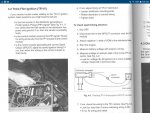
With SPOUT connector Unplugged to check base timing, with the engine running at base timing, it never dies. Unfortunately, this pointed me back to the PCM as a possible cause of my fault. But, when I plugged the SPOUT connector back together, I could make the engine falter and die by gently twisting the harness. Yes! I was sure I had located the fault, and I was right. Look at the figure with the yellow spark output signal wire that is without a section of insulation. This section happens to run through a shield ground that provided a convenient ground source for the SPOUT signal.

Just the right bump in the road or vibration from the engine would provide a path of lesser resistance for the SPOUT signal, killing the coil trigger..."
...
miesk5 note either replace the harness; or the distributor. Try to buy Ford Mototorcraft. This is similar to Hesitation, Stumble, Stall, Miss, No Start, No Spark and/or Diagnostic Trouble Code (DTC) 211 TSB 95-15-11 in 93-95 (Shorts in Profile Ignition Pickup (PIP) & Spark Output (SPOUT)
"...may exhibit various driveability symptoms, such as no start, no spark, hesitation/stumble/stall/miss and/or Diagnostic Trouble Code (DTC) 211. The symptoms may occur during any drive mode or at idle. These concerns may be caused by the shielding drain wire (Circuit 48.) cutting through the insulation of, and shorting to, the Profile Ignition Pickup (PIP) wire (Circuit 395) or the spark output (SPOUT) wire (Circuit 929) near the Powertrain Control Module (PCM) 60-pin connector. A protruding wire from Splice 145 may also cause the same concern as the wire strand shorts to the PIP, SPOUT, or the foil wrap surrounding the drain wire.
 ACTION: Inspect PIP - Circuit 395 (GY/O), Ignition Ground (IGN GND) - Circuit 259 (O/R), and SPOUT - Circuit 929 (PK) for possible cut insulation from Circuit 48. Also, inspect Splice 145 - Circuit 395 (GY/O) for stray wire strands. If wire insulation is cut, exposing copper wire, repair cut insulation with 3M Mastic Tape. Refer to the following procedure for service details.
SERVICE PROCEDURE
1. Disconnect battery ground cable.
2. If vehicle has the speed control option, remove the speed control servo bracket and position it out of the way for improved access.
3. Disconnect the connector at the Ignition Control Module (ICM - formerly TFI).
4. Unbolt the 60-pin connector from the PCM and pull the wiring up to work on.
5. Remove the 1" (25.4mm) diameter convoluted tubing from the wiring assembly. The date code tag will remain taped to the convoluted tubing.
6. Remove/cut the tape of the wiring assembly. Work toward the the ICM connector (pull back convoluted tubing as needed).
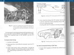
7. Unravel aluminum foil tape and electrical drain wire (Circuit 48.) from main bundle, exposing the junction or "Y" splice between the ICM tapeout and the PCM tapeout. Be careful with the foil wrap because it will be reused.
NOTE: THE FOIL WRAP LENGTH WILL BE ABOUT 5" (127mm) BEYOND THE "Y" BRANCH. THE END WILL BE TOWARD THE ICM CONNECTOR.
8. After the foil wrap is removed, look for the three (3) "grouped" wires in question at the "Y" splice. The three (3) wires are: PIP - Circuit 395 (GY/O), IGN GND - Circuit 259 (O/R), and SPOUT - Circuit 929 (PK).
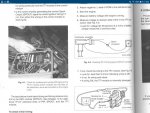
9. Locate the (bare) electrical drain wire. Wire end is toward the ICM connector, again, about 5" (127mm) from the "Y" splice. Unravel wire from the top (ICM) end and down to the area where the bare wire makes contact with the three (3) wires mentioned above.
10. Inspect for any damage to the insulation of the three (3) wires in question. If wire insulation is cut, exposing copper wire, repair cut insulation with 3M Electrical Moisture Sealant-Mastic Tape (3M Part No. 054007-06147).
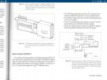
11. Inspect Splice 145 - Circuit 395 (GY/O) for stray wire strands (Figure 3). If stray wire is found, apply pressure on the wire with pliers to bend the wire down and wrap the splice with three (3) layers of flame retardant vinyl tape, or equivalent, to ensure the wire does not make contact with other wires or the foil wrap.
12. Carefully rewrap the bare electrical drain wire and foil. Work backward, toward the ICM connector end. Tape end of foil wrap to secure.
13. Retape worked area securely (between PCM and ICM connectors) with flame retardant vinyl tape, or equivalent.
14. Reinstall all convoluted tubing and tape ends of tubing to the tubing with flame retardant vinyl tape, or equivalent.
15. Reinstall PCM connector to the PCM.
16. Reinstall the ICM connector.
17. Reinstall the speed control servo bracket (two bolts) if applicable, and tighten bolts to 15-18 N-m (11-13 lb-ft).
18. Reconnect battery ground cable."
DTC 14 & 18; Profile Ignition Pickup (PIP) & Troubleshooting; "...The top three leads (for PIP signal) can lose continuity with the back plate (ground) on the module when the unit is hot. You should consider a remote mounted TFI. If your TFI is failing from heat, it can give off computer codes 14 (PIP) and 18 (SPOUT). stalling/dieing or sputtering when hot but runs when it cools off. This can be caused by a faulty TFI and the biggest culprits are heat. Another culprit can be a wire grounding out. Problematic TFI's can give off codes 14 (PIP) and 18 (SPOUT)..."
ACTION: Inspect PIP - Circuit 395 (GY/O), Ignition Ground (IGN GND) - Circuit 259 (O/R), and SPOUT - Circuit 929 (PK) for possible cut insulation from Circuit 48. Also, inspect Splice 145 - Circuit 395 (GY/O) for stray wire strands. If wire insulation is cut, exposing copper wire, repair cut insulation with 3M Mastic Tape. Refer to the following procedure for service details.
SERVICE PROCEDURE
1. Disconnect battery ground cable.
2. If vehicle has the speed control option, remove the speed control servo bracket and position it out of the way for improved access.
3. Disconnect the connector at the Ignition Control Module (ICM - formerly TFI).
4. Unbolt the 60-pin connector from the PCM and pull the wiring up to work on.
5. Remove the 1" (25.4mm) diameter convoluted tubing from the wiring assembly. The date code tag will remain taped to the convoluted tubing.
6. Remove/cut the tape of the wiring assembly. Work toward the the ICM connector (pull back convoluted tubing as needed).
7. Unravel aluminum foil tape and electrical drain wire (Circuit 48.) from main bundle, exposing the junction or "Y" splice between the ICM tapeout and the PCM tapeout. Be careful with the foil wrap because it will be reused.
NOTE: THE FOIL WRAP LENGTH WILL BE ABOUT 5" (127mm) BEYOND THE "Y" BRANCH. THE END WILL BE TOWARD THE ICM CONNECTOR.
8. After the foil wrap is removed, look for the three (3) "grouped" wires in question at the "Y" splice. The three (3) wires are: PIP - Circuit 395 (GY/O), IGN GND - Circuit 259 (O/R), and SPOUT - Circuit 929 (PK).
9. Locate the (bare) electrical drain wire. Wire end is toward the ICM connector, again, about 5" (127mm) from the "Y" splice. Unravel wire from the top (ICM) end and down to the area where the bare wire makes contact with the three (3) wires mentioned above.
10. Inspect for any damage to the insulation of the three (3) wires in question. If wire insulation is cut, exposing copper wire, repair cut insulation with 3M Electrical Moisture Sealant-Mastic Tape (3M Part No. 054007-06147).
11. Inspect Splice 145 - Circuit 395 (GY/O) for stray wire strands (Figure 3). If stray wire is found, apply pressure on the wire with pliers to bend the wire down and wrap the splice with three (3) layers of flame retardant vinyl tape, or equivalent, to ensure the wire does not make contact with other wires or the foil wrap.
12. Carefully rewrap the bare electrical drain wire and foil. Work backward, toward the ICM connector end. Tape end of foil wrap to secure.
13. Retape worked area securely (between PCM and ICM connectors) with flame retardant vinyl tape, or equivalent.
14. Reinstall all convoluted tubing and tape ends of tubing to the tubing with flame retardant vinyl tape, or equivalent.
15. Reinstall PCM connector to the PCM.
16. Reinstall the ICM connector.
17. Reinstall the speed control servo bracket (two bolts) if applicable, and tighten bolts to 15-18 N-m (11-13 lb-ft).
18. Reconnect battery ground cable."
DTC 14 & 18; Profile Ignition Pickup (PIP) & Troubleshooting; "...The top three leads (for PIP signal) can lose continuity with the back plate (ground) on the module when the unit is hot. You should consider a remote mounted TFI. If your TFI is failing from heat, it can give off computer codes 14 (PIP) and 18 (SPOUT). stalling/dieing or sputtering when hot but runs when it cools off. This can be caused by a faulty TFI and the biggest culprits are heat. Another culprit can be a wire grounding out. Problematic TFI's can give off codes 14 (PIP) and 18 (SPOUT)..."
...
DTC 29 - Insufficient input from vehicle speed sensor.
Vehicle Speed Sensor (VSS) problem (clear memory and test drive to confirm). Bad or unplugged VSS,
See overview @
http://www.fuelinjectedford.com/page33.html by Ryan M.
VSS
Location pics in a 90 - transfer case tail housing
Source: by BlueBeast (The Beast), JP N) @ http://www.supermotors.net/clubs/superford/registry/308/27536-2
See Ryan's recovered site @
http://www.fuelinjectedford.com/page1.html
...
DTC 54; the Intake Air Temp (IAT), (Air Charge Temperature [ACT] prior to 1992) sensor out of range. This one could be due to the engine not being warmed up prior to code test or suspect bad connector, shorted sensor, harness. This sensor has 5v supplied to it (Voltage Reference (VREF) is a conditioned regulated constant 5v DC power source supplied by the PCM}, and returns a signal voltage based on temperature. If voltage from this sensor reads above 4.6v, the PCM sets the code. Overview & Testing; "...This measures the temperature of the air entering the engine. Which impacts the fuel ratio; the cooler the incoming air is the denser it is. Denser air can utilize more fuel, giving us even greater accuracy in obtaining our desired air to fuel ratio. Before you start blaming the air charge temperature sensor and replacing it make sure the rest of the coolant system is in good condition. All of the following items will affect the ACT; Coolant level, Radiator Fan, Engine Temperature. READ MORE about this and the ACT TEST, by Ryan M (Fireguy50) at http://www.fuelinjectedford.com/page29.html
...