Assistance needed with post engine swap mess

Disclaimer: Links on this page pointing to Amazon, eBay and other sites may include affiliate code. If you click them and make a purchase, we may earn a small commission.

smptx

New member
Joined
Jul 22, 2012
Messages
25
Reaction score
0
I bought a 1989 FS Bronco 302, 5.0 Eddie Bauer with auto transmission. During the test drive, the owner said it had been setting up for a while and needed a fuel filter. The engine would idle at 1200 RPMs, go about 2 city blocks and die. CE light was not on because the bulb had been taken out. Replaced bulb and CE light comes on. I changed the fuel filter and discovered a rusty/stinky gasoline in the system. After siphoning out the nasy fuel, I placed a can of Seafoam in the tank and 8 fresh gallons of fuel.

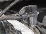
After buying it, drove it home (2 miles away) , died a few times on the way, and never got above the speed limit of 35. After arriving home, inspected the engine again to discover a swap had been made from the original 1989 302 to another 302 with a slight difference in the intake. Who ever performed the swap left off vac hoses, emission hoses, have some vac lines mixed up and hooked up to places they probably shouldn’t be. A vac (?) line comes out of right front of intake (between air intake hoses and goes to an inoperative cruise control module. If this line has not been removed after engine warm-up, it will die. [And] then,once removed, engine will stay running but idles between 1200 to 1700 RPMs (See pics A, B) .

I also discovered that the “ACT” sensor, which should be installed in the lower intake near fuel rail, is installed in a coolant pipe on top front of engine (same pipe that coolant sensor comes out of – see pic “D”). No hole exists for the ACT, another reason to believe this intake is off a newer engine where the ACT (or now “MAF”) is located in the breather box. Lots of temp differences.

After throwing a lot of money at replacing, spark plugs/wire, rotor and cap, I found this site which has a vast amount of helpful information. I have used the search engine to pull up similar problems and compared them to mine (even learned how to pull codes). Showing KOEO 54, 28, 24

I am at an impasse with how/where to go from here. I do not know exactly which year model engine I have. Pulled the started and cleaned the block above starter but I do not find any alphanumeric info. Research shows I should have a 4 alphanumeric code, a dash, followed by another 4 alphanumeric code. All I have is a bunch of letters/numbers stamped straight/sideways and within a circle (does that make sense?) If one were to spread them out, it would be something like “33F1SBBS” (See pic “C). Some say off a 91 302 T-Bird, some say the “newer” engine after the 1989’s 302. It definitely has a different intake.

So, I have an engine that I have no idea to reference an exact “where to” on vac and emission system lines, an ACT sensor installed in the coolant system, a *** coming out of intake between air hoses, and now since I tried to adjust the idle with the idle ***** near throttle cable, the vehicle floods really easy and wont restart for 5 to 6 hours.

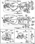
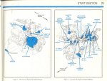
Looking for pictures please (not diagrams – since not a fully known year model specked out engine compartment) of “what goes where” considering everything under the hood (vac cans, emission cans, computer, etc), except engine, is set up for a 1989 302 5.0L with and engine/intake which looks like off a newer model. I figured that at this point if my vac and emission hoses were correct, then I can run tests on vac and sensors.

Any 89 FSB owners in the Sugar Land, TX area or any other ideas? Shops in the area not into experimenting with parts, but who are familiar with the FS Bronco's? Can't drive it (when running)- state inspection expired 2009 - won't pass smog tests with rats nest setup under hood.

Pic_A.jpg
Pic_B.jpg
Pic_C.jpg
Pic_D.jpg


Look below, identify and what should be correctly hooked up to this vac-like port? Maybe a Vapor Purge Valve? No wiring connector avalilable. 1989 302 didnt come with one, implant probably requires it?

Pic_E-2.jpg


Last edited by a moderator:

Rons beast

Active member
Joined
Dec 13, 2007
Messages
1,537
Reaction score
13
Location
Florida..in my mind , sitting on the beach
This sounds like a mess, coated with misery wrapped in a nightmare.

The ACT sensor is to gather AIR temp. not water temp. But you say it's tapped into a coolent passage!!??

I think the first order is to find the year of the engine, intake, and heads, to see if the comp. (EEC) can work with the engine.

I cannot find any info on the numbers you show.

 
Last edited by a moderator:

Rons beast

Active member
Joined
Dec 13, 2007
Messages
1,537
Reaction score
13
Location
Florida..in my mind , sitting on the beach
Your 3 codes all relate to Air intace temp and Vane temp sensor out of range. If you can get the ACT sensor in the airbox, that may correct one of the problems. Then get a vacuum diagram and rout all the hoses correct. I know some others on here have the diagrams they may share.

Some of your numbers do elude to a 91 Tbird engine, but the 4code "B"decodes to "body and electric product engineering" ??

 
OP
OP
S

smptx

New member
Joined
Jul 22, 2012
Messages
25
Reaction score
0
Thanks for the info BroncoCommander. Some one just sent me this pic, helps to solve one of the problems and confirm that the intake on my 89 is from a 94/12 or newer. Problem is, need to identify the part in the picture below and find out where it is mounted and what other hoses go to it . . .

Pic_E-1.jpg


Last edited by a moderator:

Elmo

Member
Joined
Dec 2, 2008
Messages
417
Reaction score
1
Location
Forsyth Georgia
i have a 90 with a 351w i will try to get some pics of my engine maybe they will help. but for now the ****** protruding from between the intake hoses does indeed connect to a canister( fuel vapor canister/charcoal canister) purge silinoid. i cant tell you when said silinoid would open but mine is in place but the end that would go to the canister and the canister itself are gone. so if/when the silinoid does open all it gets is fresh air and i have no codes or problems driving. so with all that said i bet if you were to cap that ****** you would suffer no ill effects. ACT=Air Charge Temp, ECT= Engine Coolant Temp. If i were in your shoes i would try to find a F150 or Bronco of the same year with the setup that yours HAD to compare yours to so you will know what you have that you dont need and to discover what you dont have that you do need as far as wireing hose routing and sensor placement.


miesk5

96 Bronco 5.0
Staff member
Moderator
Joined
Oct 18, 2005
Messages
9,071
Reaction score
1,019
Location
Floating in the Pacific
yo smptx,

re; "If this line has not been removed after engine warm-up, it will die. [And] then,once removed, engine will stay running but idles between 1200 to 1700 RPMs:

High Idle Preliminary Checks; Vacuum Leaks, Throttle Plate & Linkage, Speed Control Chain Binding/Sticking, Air Intake Tube/ Intake Manifold Leaks

That Cruise Controil Vacuum Tank and /or vac line may be leaking. Same for all other vacuum line and components (PCV, HVAC lines and dedicated vac tank, Emission components (EGR, EVP, EVR, TAD & TAB solenoids...)

==========

In pic A, look below at my reply to Pic E

& see the vac line diagram in Cruise (Speed) Control (Vacuum) Description & Operation, Diagnosis & Testing, Parts Break-Out Diagram, Removal & Installation Page 37-01-16

and same one from a 93

93CruiseVacuum.jpg

=============

PIC B

I believe the vac hose goes to the Cruise Vac Tank

cruise-vacuum-reservoir.jpg

Vacuum Reservoir Can (Tank) Port Identification pic in a 90 by Seattle FSB (SeattleFSB

============

PIC C

Will try to get back to this later; Comcast is flakey here again

================

PIC D

IAC Location pic

6-remove-iac-plug.jpg

by Xris

SENSOR Location Diagram & Depictions in 87-91 (from Factory Manual and the Ford Electrical & Vacuum Troubleshooting Manual (EVTM)

Source: by Broncobill78 (Dave) at Ford Bronco Zone Forums

87-91sensorslocationdiagram.jpg

Engine Coolant Temperature (ECT) Sensor Location pic; ECT & Temperature Gauge Sending Unit; (GT40 lower intake manifold)

gt40-lower-intake.jpg

Source: by Gacknar

Manifold Absolute Pressure (MAP); used only in Speed Density Systems Locatin pic; on firewall, pass sie

1414197_img.jpg

by JEM

+++++++++++++++++

In PIC E; "Look below, identify and what should be correctly hooked up to this vac-like port? Maybe a Vapor Purge Valve? No wiring connector avalilable. 1989 302 didnt come with one, implant probably requires it?"

That is most likely the Vacuum Line Port to the Canister Purge Solenoid (CANP) - both like and CANP shown in this pic by Seattle Bronco

p6130044a.jpg

Some more Emission ID pics by Seattle Bronco

tab-tad-evr-coil.jpg

egr-evp.jpg

==============

In last photo, that is a 96's Vapor Management Valve; located on passenger side firewall, high in my 96 with OBD II; it replaced the Canister Purge Solenoid Valve (CanP/CPRV) used in EEC IV

This is it in my 96 5.0

IMG_0920.JPG

Someone threw it in da mix.

==========

DTC 54; the Intake Air Temp (IAT), (Air Charge Temperature [ACT] prior to 1992) sensor out of range. This one could be due to the engine not being warmed up or suspect bad connector, shorted sensor, harness. This sensor has 5v supplied to it (Voltage Reference (VREF) is a conditioned regulated constant 5v DC power source supplied by the PCM}, and returns a signal voltage based on temperature. If voltage from this sensor reads above 4.6v, the PCM sets the code. Overview & Testing; "...This measures the temperature of the air entering the engine. Which impacts the fuel ratio; the cooler the incoming air is the denser it is. Denser air can utilize more fuel, giving us even greater accuracy in obtaining our desired air to fuel ratio. Before you start blaming the air charge temperature sensor and replacing it make sure the rest of the coolant system is in good condition. All of the following items will affect the ACT; oolant level, Radiator Fan, Engine Temperature. READ MORE, by Ryan M (Fireguy50) at http://oldfuelinjection.com/?p=29

Source: by miesk5 at Ford Bronco Zone Forums http://broncozone.com/topic/22532-surging-idle/

DTC 24 ACT sensor out of self test range 0.3 to 3.7 volts. Source: by Ford via Ben Watson in How to Tune and Modify Ford Fuel Injection

DTC 28 Loss of Ignition Diagnostic Monitor

check wiring and all connectors @ ICM and coil; and grounds

Ignition Diagnostic Monitor (IDM) Resistor, 22K Ohm Overview & pic; "...This 22,000 ohm resistor is connected to the negative terminal of the coil primary in the Ignition Diagnostic Monitor (IDM) circuit connected to the PCM. Every time the PCM sends a SPOUT signal to the module to fire the coil, the PCM expects to see a voltage signal on the IDM line telling it the coil actually fired. If there’s no confirmation signal on the IDM circuit after the SPPOUT signal is sent, the computer assumes that a misfire has occurred, and stores a trouble code. Don’t confuse the IDM with the operation of the OBD II Misfire Monitor..."

Source: by wrenchead.ca

=========

I'll be back later.

Wiring Diagrams in an 89

Source: by Seabronc (Rosie, Fred W) at Ford Bronco Zone Forums http://broncozone.com/topic/21145-89-bronco-help/

Wiring Diagram in an 89

bronco-1989-ignition-system--pg-28.gif

Thick Film Ignition (TFI); Ignition Module, also called the Ignition Control Module (ICM);

Source: by Seattle Bronco


Attachments

  • IMG_0920.JPG
    IMG_0920.JPG
    47.5 KB · Views: 3
  • 93CruiseVacuum.jpg
    93CruiseVacuum.jpg
    52.6 KB · Views: 3
  • 87-91sensorslocationdiagram.jpg
    87-91sensorslocationdiagram.jpg
    338.1 KB · Views: 3

miesk5

96 Bronco 5.0
Staff member
Moderator
Joined
Oct 18, 2005
Messages
9,071
Reaction score
1,019
Location
Floating in the Pacific
yo,

Some 89 5.0 info & PIC LINKs

Vehicle Emission Control Information (VECI) Decal; Contains Vacuum Diagram & Calibration Parts List for 88 & UP. On-Line for Free at Ford. Click "Quick Guides" in left panel; Scroll to & CLICK VECI Labels "Provides Vehicle Emission Control Information (VECI) and a related calibration parts list." Enter applicable info (need to know your Calibration number (also called catch code) from your B-pillar sticker). Vacuum Diagram is the same as the one on the core support or hood or air filter cover. Suggest Right Clicking this Hot Link & Open in New Window

Source: by Ford @ http://www.motorcraftservice.com/vdirs/retail/default.asp?pageid=&gutsid=&kevin=rules

Also look at the EEC (aka Computer or PCM) on PCM & Drivers side kick panel for your specific calibration code (aka catch code). See http://oldfuelinjection.com/?p=17 By Ryan M

==========

Acronyms & Color Codes; EMISSION: Red = Main vacuum; Green = EGR function; Orange = Heat control Valve (exhaust & intake) (AKA heat riser but more complex); Yellow = from the TAD Solenoid (driver's side Forward Solenoid) to the TAD (Diverter) Valve located at the rear of the Intake Manifold (Distributor Advance in Carbureted Engines); White = EGR vacuum (source); Black = Mainly used for the Evaporative emissions control; Black = Thermactor ACV or Diverter valve; Blue = Throttle Kicker control; Pink = from the TAB Solenoid (driver's side rear solenoid) to the bottom of the Thermactor Air Bypass Valve (TAB or BPV/AIR Bypass (AIRB) valve); ACV (Air Control Valve) is the TAD (Thermactor Air Diverter) Valve (AIR Bypass (AIRB) and AIR Diverter (AIRD) valve combinations); MAN VAC is Manifold Vacuum; FPR is Fuel Pressure Regulator; EGR is Exhaust Gas Re-circulation Valve SOL V: Thermactor Air Diverter (TAD) Solenoid (SOL V) (AIRD) & Thermactor Air Bypass (TAB) Solenoid; ; EVR is EGR Vacuum Regulator; VRESER is the Vacuum Reservoir Can (Tank); V REST on later years is Vapor Valve (Roll-Over @ Gas tank); V REST on earlier years such as 78/79 & SEABRONC's 83 is a Vacuum Restictor/Delay Valve, it restricts vacuum for a certain amount of time, on most engines a vacuum line from the carburetor base runs to a T & then to V REST to the distributor; Carbon Can is Carbon Canister (Charcoal Canister, Vapor Canister, Evaporative Emission (EVAP) Canister); MAP is Manifold Absolute Pressure Sensor; AIR BPV is the AIR Bypass (AIRB) Valve, also called the TAB (Thermactor Air Bypass) Valve; CPRV is Canister Purge Solenoid Valve/ Canister Purge Solenoid (CANP); VCKV is Vacuum Check Valve; vacuum check valve blocks airflow in one direction and frees airflow in the other direction. The check side of this valve will hold the highest vacuum seen on the vacuum side. If not, replace it. CAT is catalytic converter; ENG is engine; PCV is Positive Crankcase Ventilation Valve. HVAC in 92-96; Black = from engine source to vacuum check valve & to vacuum reservoir tank & to Control Panel; White = actuates the Outside/Recirc air door two-position vacuum control motor; Blue = Mix (actuates the FLOOR/PANEL air door two-position vacuum control motor); Red = Floor Flow & Yellow = Panel, (actuate the FLOOR/DEFROST three-position air vacuum control motor). READ MORE

Source: by Seabronc (Rosie, Fred W), Seattle FSB Steve & miesk5 at Ford Bronco Zone Forums http://broncozone.com/topic/20593-small-vacuum-line/

Coolant Line From Radiator to Throttle Body Removal in an 89 5.0

Source: by Waltman at http://www.supermotors.net/registry/10222/55357

EGR & EVP (on top, white) Location pic in an 89 5.0 at the EGR Valve (part of his valve cover and oil pan gasket job); "...Then I removed the egr pipe from the egr; BE CAREFUL HERE. USE PENETRATING FLUID HERE PRIOR TO REMOVAL. i BROKE ONE ON MY LAST BRONCO AND I HAD TO BUY A NEW ONE FROM THE DEALER FOR ALMOST $100..."

Source: by Waltman at SuperMotors.net

change-oil-pan-gasket-and-valve-cover-gasket-024.jpg

==============

 
Last edited by a moderator:

miesk5

96 Bronco 5.0
Staff member
Moderator
Joined
Oct 18, 2005
Messages
9,071
Reaction score
1,019
Location
Floating in the Pacific
yo, Had to copy and cut this info hec I had error messages about too many pics

Vacuum Hose (Line) Replacement w/Rubber Hose in an 89 F 150 5.0 ABOUT 99.999 = to Bronco); "...This should cover most 87-96 V8s (302\351); for the I6s (300)s the solenoids are in the same general area, as well as the valves. You can use this article as a basis to replace yours, just keep in mind it..."

emissionsv8.jpg

You can see the yellow line going to the "diverter" valve (TAD). You can also see

the “bypass” valve (TAB) (you can't see the vacuum line going there, but when you

look at it on your truck you'll see it), plus the EGR and all that other stuff.

Ok, so now that we have an idea of what goes on, let's get started. To avoid confusion,

only run one hose at a time. We need to replace\rerun the red vacuum line, so take a

piece of vacuum hose and run it from the vacuum tree on the intake manifold to

the vacuum canister.

Here's a drawing\breakdown of the EVR solenoid (the TAB\TAD are basically the same):

EVR_EGR.gif


miesk5

96 Bronco 5.0
Staff member
Moderator
Joined
Oct 18, 2005
Messages
9,071
Reaction score
1,019
Location
Floating in the Pacific
Seattle Bronco wrote; "I found the Cruise Control diaphram was leaking as well and temporarily capped it..."

vacuum-9.jpg

& IAC (Idle Air Controller). Many threads on removing, cleaning and replacing this

idle-air-controller-(iac).jpg

& one-way vacuum line that comes from the vacuum tree and branches off twice to the HVAC. I did not replace the second line as it goes through the firewall.

p1010012.jpg

& line from the charcoal filter is for fuel vapor from the tank. It uses fuel resistant rubber and goes to the Cannister Purge Solenoid (CANP).

carbon-canister.jpg

& A vacuum from comes from the Intake Manifold tee, to the coffee can vacuum reservoir and then goes out the can to the bottom of the solenoids in parallel. Then the top line on the solenoids go out to the TAB/TAD/EGR.

vacuum-14.jpg

& That is the Canister Purge Solenoid (CANP). For emissions, fuel vapors are drawn from the fuel tank and are routed to a Charcoal Element Canister. The charcoal absorbs any liquid fuel and vapors are routed to the Throttle Body (Intake) to be reburned, upon command from the EEC. This is because venting vapors into the atmosphere is a major cause of pollution. The line you refer to is fuel resistant rubber as hydrocarbons will break down silicone and other non-approved materials. In other words, that is a Fuel Vapor Line not a Vacuum Line.

mmfp_0801_09_z+charcoal_canister+.jpg


miesk5

96 Bronco 5.0
Staff member
Moderator
Joined
Oct 18, 2005
Messages
9,071
Reaction score
1,019
Location
Floating in the Pacific
========

Wiring Diagrams in 87-89 Bronco & F series (Mitchell); miesk5 Note; in an 89, G801 is located on the LH inner fender behind the headlamp & both pumps Grounds join @ Splices S155 & S903; (at pumps); Wiring Diagrams in 87-89 Bronco & F series (Mitchell); MIESK5 Note, page 2 shows the 4.9 EEC and injectors, etc.; page 3 and on

Source: by equivalent (Beetlejuice) at http://www.supermotors.net/registry/media/280829

EEC Ground Location pic in an 89; "...After tracking down the no-start condition due to afore mentioned blown fusible link, and tracking down a no-spark situation due to afore mentioned unplugged timing gun, I spent 2 days and alot of phone calls, and alot of conversations with Ford mechanics learning how my injectors fire and what makes them fire since my injectors werent firing. The techs at the Ford dealership in Mooresville pulled out all the books and after about 4 of them talked about it for a few minutes one of them pointed to 2 grounds and said check these, these will make your EEC do crazy things...and damn if one of them wasnt connected. & Those wires eventually connect back to the EEC case (which is grounded) and the pins on the connector that need to be grounded...but then again every ground connects to each other on a Bronco..."

img_0346.jpg

Source: by Will H (kf4amu, The Beast) at SuperMotors.net

EGR Vacuum Regulator (EVR), Thermactor Air Bypass (TAB) Solenoid (AIRB) & Thermactor Air Diverter (TAD) Solenoid (AIRD) Wiring Diagram in an 89 5.0, 5.8 & 7.5. Diagram #2

Source: by Seabronc (Rosie, Fred W) at Ford Bronco Zone Forums http://broncozone.com/topic/20547-fuel-pump-wont-shut-off/

Wiring Diagram s, Ignition, Emission, EFI, Sensors, Fuel Level Sender & Pump, etc. in Electrical and Vacuum Troubleshooting Manual (EVTM) Partial, Wiring Diagrams in an 89

Source: by SeattleFSB (Seattle FSB) at http://www.supermotors.net/registry/20487/76449


miesk5

96 Bronco 5.0
Staff member
Moderator
Joined
Oct 18, 2005
Messages
9,071
Reaction score
1,019
Location
Floating in the Pacific
Cruise Control Servo Adjustments & Removal in an 89; "...1.Snap the molded cable retainer over the accelerator cable end fitting attached, to the throttle ball stud. 2.Remove the adjuster retainer clip, if installed, from the adjuster mounting tab. 3.Insert the speed control actuator cable adjuster mounting tab in the slot provided in the accelerator cable support bracket. 4.Pull the cable through the adjuster until a slight tension is felt without opening the throttle plate. 5.Insert the adjuster cable retainer clip slowly, until engagement is felt, then, push it downwards until it locks in position. Removal; 1.Disconnect the wiring at the servo. 2.Disconnect the adjuster from the accelerator cable. 3.Disconnect the vacuum line at the servo. 4.Remove the actuator cable-to-bracket *****. 5.Remove the pins and nuts retaining the servo to its mounting bracket and lift it out..."

Source: by Chilton via miesk5 at Ford Bronco Zone Forums http://broncozone.com/topic/20961-cruise-control-not-working/page__gopid__112305&

Run it around the back of the engine (I ran it on top of the passenger side valve cover,

under the upper intake plenum). Plug the hose into the vacuum canister where the red

hose plugged into. Here's an overhead pic of how I have my vacuum lines run, you can

also use this to see how to run new (rubber) lines to the FPR (Fuel Pressure Regulator)

and the MAP (Manifold Absolute Pressure) Sensor. In all my pics I tried to use the most

sophisticated graphic design program known to man (Paint) to help. I tried to keep the

coloring the same as the original colors, with the exception of the MAP sensor and FPR:


miesk5

96 Bronco 5.0
Staff member
Moderator
Joined
Oct 18, 2005
Messages
9,071
Reaction score
1,019
Location
Floating in the Pacific
More by Booba

Go back to the driver side of the intake, where the solenoids are, and cut the vacuum line

you just ran so you can put a "T" on it and run a very short vacuum line to the bottom of

the EVR\EGR solenoid:

MainTcolor.jpg

From the T you connect a short vacuum hose to the bottom of the EVR solenoid, Pic

EGRcolor2.jpg

run a vacuum hose from the top of the EVR solenoid where the green line used to be

(see pic above) to your EGR valve. I ran the hose through the hole in the middle of the intake plenum, and then ran it up to the EGR

Now go back to the vacuum canister, and run a vacuum hose from the OTHER plug on the

canister(formerly black line) to the bottom port on the 2 solenoids for TAB\TAD. You will

need another "T" so that you can split the hose into 2 hoses, one for each solenoid.

Kind of hard to see in this pic, you can see the white tip of the T, but it'll make sense

when your doing it:

Accolor.jpg

 
Last edited by a moderator:

miesk5

96 Bronco 5.0
Staff member
Moderator
Joined
Oct 18, 2005
Messages
9,071
Reaction score
1,019
Location
Floating in the Pacific
2 hoses coming from the vacuum canister (A.C. stands for After Canister):

Canistercolor.jpg

After that, run a hose from the top port on the TAD (front of the 2 solenoids) to the diverter

valve behind the intake plenum (originally it was a yellow hose). Here's a pic, I literally

set my camera on the intake plenum, and took a picture behind it; so it's kind of close up:

Tadcolor.jpg

All that's left is to run a vacuum hose from the top port of the rear-most solenoid (TAB)

to the valve that’s right by the smog pump. This was the hardest part for me, but I have

fat fingers, and truthfully it wasn't that bad; just annoying. Here's a pic, it might be easier

to plug the hose in from under the truck, but I was able to do it from the top.

TABColor.jpg

TABfromFrame.jpg

Here's the solenoids with the TAD, TAB, and the A.C. (After Canister) line

TABTADC.jpg


miesk5

96 Bronco 5.0
Staff member
Moderator
Joined
Oct 18, 2005
Messages
9,071
Reaction score
1,019
Location
Floating in the Pacific
That’s it for the SMOG stuff, but if you want to completely do away with all the plastic ***** you can run a new hose from the vacuum tree straight to the FPR (fuel pressure regulator),as well as a vacuum hose straight from the vacuum tree to the MAP sensor.

Here's some pics of the whole set up, you can see the hoses going to the solenoids

overall2.jpg

You can see the hoses on the inlet\outlet of the EVR solenoid here (same pic as prev posted):

http://i14.photobucket.com/albums/a304/booba5/EGRMain.jpg

========

Wiring Diagrams in 87-89 Bronco & F series (Mitchell); miesk5 Note; in an 89, G801 is located on the LH inner fender behind the headlamp & both pumps Grounds join @ Splices S155 & S903; (at pumps); Wiring Diagrams in 87-89 Bronco & F series (Mitchell); MIESK5 Note, page 2 shows the 4.9 EEC and injectors, etc.; page 3 and on

Source: by equivalent (Beetlejuice) at http://www.supermotors.net/registry/media/280829

 
Last edited by a moderator:

miesk5

96 Bronco 5.0
Staff member
Moderator
Joined
Oct 18, 2005
Messages
9,071
Reaction score
1,019
Location
Floating in the Pacific
EEC Ground Location pic in an 89; "...After tracking down the no-start condition due to afore mentioned blown fusible link, and tracking down a no-spark situation due to afore mentioned unplugged timing gun, I spent 2 days and alot of phone calls, and alot of conversations with Ford mechanics learning how my injectors fire and what makes them fire since my injectors werent firing. The techs at the Ford dealership in Mooresville pulled out all the books and after about 4 of them talked about it for a few minutes one of them pointed to 2 grounds and said check these, these will make your EEC do crazy things...and damn if one of them wasnt connected. & Those wires eventually connect back to the EEC case (which is grounded) and the pins on the connector that need to be grounded...but then again every ground connects to each other on a Bronco..."

img_0346.jpg

Source: by Will H (kf4amu, The Beast) at SuperMotors.net

EGR Vacuum Regulator (EVR), Thermactor Air Bypass (TAB) Solenoid (AIRB) & Thermactor Air Diverter (TAD) Solenoid (AIRD) Wiring Diagram in an 89 5.0, 5.8 & 7.5. Diagram #2

Source: by Seabronc (Rosie, Fred W) at Ford Bronco Zone Forums http://broncozone.com/topic/20547-fuel-pump-wont-shut-off/

Wiring Diagram s, Ignition, Emission, EFI, Sensors, Fuel Level Sender & Pump, etc. in Electrical and Vacuum Troubleshooting Manual (EVTM) Partial, Wiring Diagrams in an 89

Source: by SeattleFSB (Seattle FSB) at http://www.supermotors.net/registry/20487/76449

Cruise Control Servo Adjustments & Removal in an 89; "...1.Snap the molded cable retainer over the accelerator cable end fitting attached, to the throttle ball stud. 2.Remove the adjuster retainer clip, if installed, from the adjuster mounting tab. 3.Insert the speed control actuator cable adjuster mounting tab in the slot provided in the accelerator cable support bracket. 4.Pull the cable through the adjuster until a slight tension is felt without opening the throttle plate. 5.Insert the adjuster cable retainer clip slowly, until engagement is felt, then, push it downwards until it locks in position. Removal; 1.Disconnect the wiring at the servo. 2.Disconnect the adjuster from the accelerator cable. 3.Disconnect the vacuum line at the servo. 4.Remove the actuator cable-to-bracket *****. 5.Remove the pins and nuts retaining the servo to its mounting bracket and lift it out..."

Source: by Chilton via miesk5 at Ford Bronco Zone Forums http://broncozone.com/topic/20961-cruise-control-not-working/page__gopid__112305&

Run it around the back of the engine (I ran it on top of the passenger side valve cover,

under the upper intake plenum). Plug the hose into the vacuum canister where the red

hose plugged into. Here's an overhead pic of how I have my vacuum lines run, you can

also use this to see how to run new (rubber) lines to the FPR (Fuel Pressure Regulator)

and the MAP (Manifold Absolute Pressure) Sensor. In all my pics I tried to use the most

sophisticated graphic design program known to man (Paint) to help. I tried to keep the

coloring the same as the original colors, with the exception of the MAP sensor and FPR:


miesk5

96 Bronco 5.0
Staff member
Moderator
Joined
Oct 18, 2005
Messages
9,071
Reaction score
1,019
Location
Floating in the Pacific
Here's the solenoids with the TAD, TAB, and the A.C. (After Canister) line

same pic as prev posted

http://i14.photobucket.com/albums/a304/booba5/TABTADC.jpg

That’s it for the SMOG stuff, but if you want to completely do away with all the plastic *****

you can run a new hose from the vacuum tree straight to the FPR (fuel pressure regulator),

as well as a vacuum hose straight from the vacuum tree to the MAP sensor.

Here's some pics of the whole set up, you can see the hoses going to the solenoids

http://i14.photobucket.com/albums/a304/booba5/overall2.jpg

same pic as prev posted

You can see the hoses on the inlet\outlet of the EVR solenoid here:

http://i14.photobucket.com/albums/a304/booba5/EGRMain.jpg

same pic as prev posted

Cruise Control Servo Adjustments & Removal in an 89; "...1.Snap the molded cable retainer over the accelerator cable end fitting attached, to the throttle ball stud. 2.Remove the adjuster retainer clip, if installed, from the adjuster mounting tab. 3.Insert the speed control actuator cable adjuster mounting tab in the slot provided in the accelerator cable support bracket. 4.Pull the cable through the adjuster until a slight tension is felt without opening the throttle plate. 5.Insert the adjuster cable retainer clip slowly, until engagement is felt, then, push it downwards until it locks in position. Removal; 1.Disconnect the wiring at the servo. 2.Disconnect the adjuster from the accelerator cable. 3.Disconnect the vacuum line at the servo. 4.Remove the actuator cable-to-bracket *****. 5.Remove the pins and nuts retaining the servo to its mounting bracket and lift it out..."

Source: by Chilton via miesk5 at Ford Bronco Zone Forums http://broncozone.com/topic/20961-cruise-control-not-working/page__gopid__112305&

Run it around the back of the engine (I ran it on top of the passenger side valve cover, under the upper intake plenum). Plug the hose into the vacuum canister where the red hose plugged into. Here's an overhead pic of how I have my vacuum lines run, you can also use this to see how to run new (rubber) lines to the FPR (Fuel Pressure Regulator) and the MAP (Manifold Absolute Pressure) Sensor. In all my pics I tried to use the most sophisticated graphic design program known to man (Paint) to help. I tried to keep the coloring the same as the original colors, with the exception of the MAP sensor and FPR:

Go back to the driver side of the intake, where the solenoids are, and cut the vacuum line you just ran so you can put a "T" on it and run a very short vacuum line to the bottom of the EVR\EGR solenoid:

http://i14.photobucket.com/albums/a304/booba5/MainTcolor.jpg

same pic as prev posted

From the T you connect a short vacuum hose to the bottom of the EVR solenoid, Pic

http://i14.photobucket.com/albums/a304/booba5/EGRcolor2.jpg

same pic as prev posted

 
Last edited by a moderator:

miesk5

96 Bronco 5.0
Staff member
Moderator
Joined
Oct 18, 2005
Messages
9,071
Reaction score
1,019
Location
Floating in the Pacific
run a vacuum hose from the top of the EVR solenoid where the green line used to be

(same pic as prev posted) to your EGR valve. I ran the hose through the hole in the middle of theintake plenum, and then ran it up to the EGR

http://i14.photobucket.com/albums/a304/booba5/EGRcolor2.jpg

same pic as prev posted

Now go back to the vacuum canister, and run a vacuum hose from the OTHER plug on the

canister(formerly black line) to the bottom port on the 2 solenoids for TAB\TAD. You will need another "T" so that you can split the hose into 2 hoses, one for each solenoid.

Kind of hard to see in this pic, you can see the white tip of the T, but it'll make sense when your doing it:

http://i14.photobucket.com/albums/a304/booba5/Accolor.jpg

same pic as prev posted

2 hoses coming from the vacuum canister (A.C. stands for After Canister):

http://i14.photobucket.com/albums/a304/booba5/Canistercolor.jpg

same pic as prev posted

e pic as aboveAfter that, run a hose from the top port on the TAD (front of the 2 solenoids) to the diverter valve behind the intake plenum (originally it was a yellow hose). Here's a pic, I literally set my camera on the intake plenum, and took a picture behind it; so it's kind of close up:

[http://i14.photobucket.com/albums/a304/booba5/Tadcolor.jpg

same pic as prev posted

All that's left is to run a vacuum hose from the top port of the rear-most solenoid (TAB) to the valve that’s right by the smog pump. This was the hardest part for me, but I havefat fingers, and truthfully it wasn't that bad; just annoying. Here's a pic, it might be easier to plug the hose in from under the truck, but I was able to do it from the top.

http://i14.photobucket.com/albums/a304/booba5/TABColor.jpg

same pic as prev posted

http://i14.photobucket.com/albums/a304/booba5/TABfromFrame.jpg

same pic as prev posted

Here's the solenoids with the TAD, TAB, and the A.C. (After Canister) line

http://i14.photobucket.com/albums/a304/booba5/TABTADC.jpg

same pic as prev posted

That’s it for the SMOG stuff, but if you want to completely do away with all the plastic ***** you can run a new hose from the vacuum tree straight to the FPR (fuel pressure regulator), as well as a vacuum hose straight from the vacuum tree to the MAP sensor.

Here's some pics of the whole set up, you can see the hoses going to the solenoids

http://i14.photobucket.com/albums/a304/booba5/overall2.jpg

same pic as prev posted

You can see the hoses on the inlet\outlet of the EVR solenoid here:

http://i14.photobucket.com/albums/a304/booba5/EGRMain.jpg

same pic as prev posted

========

Wiring Diagrams in 87-89 Bronco & F series (Mitchell); miesk5 Note; in an 89, G801 is located on the LH inner fender behind the headlamp & both pumps Grounds join @ Splices S155 & S903; (at pumps); Wiring Diagrams in 87-89 Bronco & F series (Mitchell); MIESK5 Note, page 2 shows the 4.9 EEC and injectors, etc.; page 3 and on

Source: by equivalent (Beetlejuice) at http://www.supermotors.net/registry/media/280829

EEC Ground Location pic in an 89; "...After tracking down the no-start condition due to afore mentioned blown fusible link, and tracking down a no-spark situation due to afore mentioned unplugged timing gun, I spent 2 days and alot of phone calls, and alot of conversations with Ford mechanics learning how my injectors fire and what makes them fire since my injectors werent firing. The techs at the Ford dealership in Mooresville pulled out all the books and after about 4 of them talked about it for a few minutes one of them pointed to 2 grounds and said check these, these will make your EEC do crazy things...and damn if one of them wasnt connected. & Those wires eventually connect back to the EEC case (which is grounded) and the pins on the connector that need to be grounded...but then again every ground connects to each other on a Bronco..."

img_0346.jpg

Source: by Will H (kf4amu, The Beast) at SuperMotors.net

EGR Vacuum Regulator (EVR), Thermactor Air Bypass (TAB) Solenoid (AIRB) & Thermactor Air Diverter (TAD) Solenoid (AIRD) Wiring Diagram in an 89 5.0, 5.8 & 7.5. Diagram #2

Source: by Seabronc (Rosie, Fred W) at Ford Bronco Zone Forums http://broncozone.com/topic/20547-fuel-pump-wont-shut-off/

Wiring Diagram s, Ignition, Emission, EFI, Sensors, Fuel Level Sender & Pump, etc. in Electrical and Vacuum Troubleshooting Manual (EVTM) Partial, Wiring Diagrams in an 89

Source: by SeattleFSB (Seattle FSB) at http://www.supermotors.net/registry/20487/76449

Cruise Control Servo Adjustments & Removal in an 89; "...1.Snap the molded cable retainer over the accelerator cable end fitting attached, to the throttle ball stud. 2.Remove the adjuster retainer clip, if installed, from the adjuster mounting tab. 3.Insert the speed control actuator cable adjuster mounting tab in the slot provided in the accelerator cable support bracket. 4.Pull the cable through the adjuster until a slight tension is felt without opening the throttle plate. 5.Insert the adjuster cable retainer clip slowly, until engagement is felt, then, push it downwards until it locks in position. Removal; 1.Disconnect the wiring at the servo. 2.Disconnect the adjuster from the accelerator cable. 3.Disconnect the vacuum line at the servo. 4.Remove the actuator cable-to-bracket *****. 5.Remove the pins and nuts retaining the servo to its mounting bracket and lift it out..."

Source: by Chilton via miesk5 at Ford Bronco Zone Forums http://broncozone.com/topic/20961-cruise-control-not-working/page__gopid__112305&

Run it around the back of the engine (I ran it on top of the passenger side valve cover,

under the upper intake plenum). Plug the hose into the vacuum canister where the red

hose plugged into. Here's an overhead pic of how I have my vacuum lines run, you can

also use this to see how to run new (rubber) lines to the FPR (Fuel Pressure Regulator)

and the MAP (Manifold Absolute Pressure) Sensor. In all my pics I tried to use the most

sophisticated graphic design program known to man (Paint) to help. I tried to keep the

coloring the same as the original colors, with the exception of the MAP sensor and FPR:

 
Last edited by a moderator:

miesk5

96 Bronco 5.0
Staff member
Moderator
Joined
Oct 18, 2005
Messages
9,071
Reaction score
1,019
Location
Floating in the Pacific
Go back to the driver side of the intake, where the solenoids are, and cut the vacuum lineyou just ran so you can put a "T" on it and run a very short vacuum line to the bottom of

the EVR\EGR solenoid:

http://i14.photobucket.com/albums/a304/booba5/MainTcolor.jpg

same pic as prev posted

From the T you connect a short vacuum hose to the bottom of the EVR solenoid, Pic

http://i14.photobucket.com/albums/a304/booba5/EGRcolor2.jpg'>http://i14.photobucket.com/albums/a304/booba5/EGRcolor2.jpg

same pic as prev posted

run a vacuum hose from the top of the EVR solenoid where the green line used to be

(same pic as prev posted) to your EGR valve. I ran the hose through the hole in the middle of theintake plenum, and then ran it up to the EGR

http://i14.photobucket.com/albums/a304/booba5/EGRcolor2.jpg

same pic as prev posted

Now go back to the vacuum canister, and run a vacuum hose from the OTHER plug on the

canister(formerly black line) to the bottom port on the 2 solenoids for TAB\TAD. You will need another "T" so that you can split the hose into 2 hoses, one for each solenoid.

Kind of hard to see in this pic, you can see the white tip of the T, but it'll make sense when your doing it:

http://i14.photobucket.com/albums/a304/booba5/Accolor.jpg

same pic as prev posted

2 hoses coming from the vacuum canister (A.C. stands for After Canister):

http://i14.photobucket.com/albums/a304/booba5/Canistercolor.jpg

same pic as prev posted

After that, run a hose from the top port on the TAD (front of the 2 solenoids) to the diverter valve behind the intake plenum (originally it was a yellow hose). Here's a pic, I literally set my camera on the intake plenum, and took a picture behind it; so it's kind of close up:

http://i14.photobucket.com/albums/a304/booba5/Tadcolor.jpg

All that's left is to run a vacuum hose from the top port of the rear-most solenoid (TAB) to the valve that’s right by the smog pump. This was the hardest part for me, but I have fat fingers, and truthfully it wasn't that bad; just annoying. Here's a pic, it might be easierto plug the hose in from under the truck, but I was able to do it from the top.

http://i14.photobucket.com/albums/a304/booba5/TABColor.jpg

http://i14.photobucket.com/albums/a304/booba5/TABfromFrame.jpg

Here's the solenoids with the TAD, TAB, and the A.C. (After Canister) line

http://i14.photobucket.com/albums/a304/booba5/TABTADC.jpg

 
Last edited by a moderator:

Members online

No members online now.

Forum statistics

Threads
22,520
Messages
135,980
Members
25,124
Latest member
Fryman22
Top