yo,
GROUNDS; in a 96 & others in 92-96 range, but most are = to the 93, exc for MAF, Misfire.
G101 front of engine compartment, front of fender apron (D1) - RH = Passenger side mine has 2 small black wires between starter relay & headlight; this is #5 in the diagram; G100 & G104 (tied together in diagram);
G100 @ LH front of engine compartment, on upper radiator support;
G104 @ Rear of LH fender apron near hood hinge and 4WABS Test Connector (RED);
"...The EEC-IV (computer) ground comes from two main sources, one is the body/frame ground (G104) and the other is the small black wire that goes directly to the negative terminal of the battery (G101/102). G104 goes to EEC Pin #20 and the TFI ICM. G101/102 goes to EEC Pin #40 & 60. This a direct ground to the battery(-) post and the connection on the radiator support is frequently the cause of problems. It can also corrode developing a poor connection at the negative battery cable connection at the battery post..."
Source: by Seattle FSB
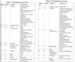
G100 Serves Component, LH Oxygen Sensor, Fuel Pump Module, Inertia Fuel Shutoff, Misfire Sensor, Misfire Sensor Shield, Powertrain Control Module (PCM) 5.0L;
G101 Serves, RH Oxygen Sensor; G104 Serves Component: 4WABS Control Module, 4WABS Data Link Connector, 4WABS Relay #1, Instrument Cluster, Powertrain Control Module (PCM) 5.8L, Powertrain Control Module (PCM) 5.8L, Programmable Speedometer/Odometer Module (PSOM), Trailer Relay Box;
G103 (battery to engine) Lower RH front of engine serves Component, 4WABS Pump Motor, Battery, Data Link Connector (DLC), Mass Air Flow (MAF) Sensor, Powertrain Control Module (PCM) 5.0L, Powertrain Control Module (PCM) 5.8L, Right Front Park/Turn Lamp, Right Front Side Marker Lamp Right Headlamp;
G201 Behind bottom of LH cowl panel (driver's side kick panel),Component, Compass/Outside Temperature Module, Day/Night Mirror, Inside Cargo Lamp, Left Power Lumbar Compressor Motor, Outside Cargo/High Mount Stop Lamps, Right Power Lumbar Compressor Motor, Seat Belt Switch, Door Lock Actuator (PDL & Probably Power Window Motor);
G200 Behind bottom of RH cowl panel serves Component, Air Bag Diagnostic Monitor, Electronic Shift Control Module, Instrument Cluster, Programmable Speedometer/Odometer Module (PSOM), Remote/Keyless Entry Module, Speed Control Servo/Amplifier Assembly; G103 (battery to engine) Lower RH front of engine serves Component, 4WABS Pump Motor, Battery, Data Link Connector (DLC), Mass Air Flow (MAF) Sensor, Powertrain Control Module (PCM) 5.0L, Powertrain Control Module (PCM) 5.8L, Right Front Park/Turn Lamp, Right Front Side Marker Lamp, Right Headlamp; G400 Rear Window Defroster @ LH rear corner of cargo area, near rear lamp assembly;
Engine Block pic in a 94 5.8; G401 LH rear corner of cargo area, near rear lamp assembly (F9); "...The black battery wire goes from the front bolt of the engine mount (on the block) to this tab & up to the battery post, where a smaller black wire goes to the core support, providing a continuous ground path between the engine, frame, battery, & body;
Frame & Battery pic in a 93; "...With the wheelwell gone, it's easy to inspect the frame ground, just inboard of the spring tower on top of the frame rail. The battery ground cable is stripped ~3/4" and a tab is soldered on so it can be bolted to the frame;
Intake Manifold to Block Strap Location in a 96 5.0 is between 2nd & 3rd plugs on passenger side; Locations & Components in a 96;
SEE DIAGRAMS
Source: by miesk5 at Ford Bronco Zone Forums
http://broncozone.com/topic/20952-loose-ground/page__pid__109954__st__0entry109954
=============
re; " it clicks once and nothing. allmost as if the engine is seized. let it set a while and cool off and it starts without a problem"
So There is NO CRANK when Hot?
And When NO CRANK, do headlights, radio or anythAng else work?
If lights, radio do not work, then check all cables and connector; look for corrosion, aside from usual between lug or connectors and engine, etc. look for it between wire starnds near connector/lug
If lights & radio work;
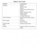
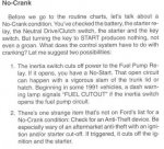
No Crank; "...For an engine-won't-crank condition with an automatic transmission (7003), determine if the condition exists with the shift control selector level in both PARK and NEUTRAL positions before performing the ignition switch continuity tests. If the no-crank condition occurs in one shift lever position but not the other, a more probable cause is the Manual Lever Position (MLPS) located on driver's side of transmission case. Ignition Switch Pin-Out Diagram & Continuity Testing (Logic Tables) in a 96; Disconnect ignition key warning switch terminal and wire from the ignition switch (11572). Test the continuity of the ignition switch as described in the following illustrations. Connect a self-powered test lamp or ohmmeter between the blade terminals indicated on the chart. No continuity between any blade and chassis ground should exist in any ignition switch position except the proof Circuit 41 (BK/LB) (Pin P1) and Circuit 512 (T/LG) (Pin P2) in the START position only. NOTE: Ignition Switch Mechanical Test: Accessories that fail to operate with the key in RUN, or that remain on when the key is turned off, may be the result of a misadjusted ignition switch rather than a malfunctioning ignition switch. Refer to Ignition Switch in the Adjustments portion of this section. Do not apply lubricant to the inside of the ignition switch. Test the steering column ignition system mechanical operation by rotating the ignition switch lock cylinder (11582) through all positions of the ignition switch. The movement should feel smooth with no sticking or binding. The ignition system should return from the START position back to the ON position without assistance (spring return). If sticking or binding is encountered, check for the following: burrs on the ignition switch lock cylinder; binding ignition switch lock cylinder; shroud rubbing against ignition switch lock cylinder; burrs or foreign material around the rack-and-pinion actuator in the housing of the ignition switch lock cylinder; insufficient **** on actuator; binding ignition switch


===============
No Start, but Cranks and or Misfire, etc.; Thick Film Ignition (TFI) Testing, Overview & Diagrams; "...This article applies to both the Gray colored Ignition Control Module and the Black colored Ignition Control Module. The Gray colored Ignition Control Module is called the Push Start Module and the Black colored Ignition Control Module is called the Computer Controlled Dwell Module. Part I; In This Fast Test you'll be able to pinpoint the problem to the Ignition Control Module or the Ignition Coil or the Profile Ignition Pickup Sensor (PIP Sensor) in four easy test steps. This test will only help you in a Cranks but Does Not Start Condition. So then, before starting the tests, it's critical that you have checked and verified that there's NO SPARK present at the Ignition Coil. Why? Well, because if the Ignition Coil is sparking, it would be a clear indication that it and the Ignition Coil and the Crankshaft Position Sensor (PIP Sensor) are working.
The Ford Distributor Mounted Ignition Control Module Test and PIP Sensor Test is divided into several parts, and so... to help you navigate this article, here are the contents of this article at a quick glance:
◦How Does the Ignition Control Module Work?
◦What Tools do I Need for the Ignition Module Test?
◦TEST INFO Circuit Descriptions
◦TEST 1 Checking for Power (12 V)
◦TEST 2 Testing the Ground Circuit
◦TEST 3 Ignition Coil Switching Signal
◦TEST 4 Testing the PIP Signal
READ MUCH MORE http://easyautodiagnostics.com/ford_ignition_module/distributor_mounted_module_1.php
===========


