misfire nightmare

Disclaimer: Links on this page pointing to Amazon, eBay and other sites may include affiliate code. If you click them and make a purchase, we may earn a small commission.

mattafact

New member
Joined
Dec 12, 2010
Messages
1
Reaction score
0
hello everyone, i just bought a 93 bronco with the gas friendly 5.8, i bought it a week ago and ever since ive been replacing and testing everything possible but no matter what i do the engine misfires in multiple cylinders.

heres what ive done so far:

replaced:

plugs

cap

rotor

wires

coil

fuel pump

2 fuel injectors

fuel press regulator

egr solenoid

iac valve

fuel filter

air filter

tested the ignition control module, came out OK.

tested fuel pressure, OK.

tested alternator output, OK.

the injector wire for #5 cylinder was chewed up, i bought a new connector and replaced it

im running out of things to fix, and i still cant figure out why this thing misfires.

i hooked up a spark plug tester and found that almost every cylinder is misfiring, i soaked the connections to see if anything was arcing, everything was ok.

i hope im forgetting something because ive done as much as i can think of to fix it to no avail. anyone have any ideas?


Seabronc

New member
Joined
May 22, 2004
Messages
7,315
Reaction score
35
Location
North of NYC
I don't see anything here about having done the basic timing setup. That is done with the SPOUT connector removed.

Good luck,

:)>-


BUCKIN'94WFO

New member
Joined
Mar 27, 2009
Messages
43
Reaction score
6
Location
Dallas Texas
I think I'd pull the cap and try to wiggle the distributor shaft. Sounds like you could have a worn out shaft bushing or even crud on the Hall effect.(ignition module inside the distributor)


miesk5

96 Bronco 5.0
Staff member
Moderator
Joined
Oct 18, 2005
Messages
9,071
Reaction score
1,019
Location
Floating in the Pacific
yo,

I go w/Seabronc & Buck' on both possibilites and thias well;

Spark Plug Wire Routing & Firing Order TSB 94-04-10 for 87-93 5.0 & 94-96 5.0 & all 5.8 - engine miss, spark knock, buck/***** surge and other driveability concerns;

MIESK5 NOTE; The firing order for 1994 5.0Ls & all 5.8Ls is 1-3-7-2-6-5-4-8.

Distributor rotation: Counterclockwise

On these vehicles the #1 and #3, or #5 and #6 spark plug wires must be separated to eliminate the possibility of an induction crossfire. To eliminate the possibility of the coil wire becoming disconnected, route the coil wire under the spark plug wires at the distributor cap.

Source: by Ford

Can you try a Test for Codes?

Self Test by BroncoJoe19 do the KOEO = Key On Engine Off portion first & Remember to have engine @ Normal Operating Temperature before doing the KEY ON ENGINE RUNNING (KOER) portion

It could be due to a problem with the EGR system (other than the valve itself) causing the engine to misfire under load.

Is it misfirng under load and @ idle or...?


Seabronc

New member
Joined
May 22, 2004
Messages
7,315
Reaction score
35
Location
North of NYC
I think I'd pull the cap and try to wiggle the distributor shaft. Sounds like you could have a worn out shaft bushing or even crud on the Hall effect.(ignition module inside the distributor)
OR even the possibility of a worn timing chain.

:)>-


BroncoJoe19

Active member
Joined
Dec 26, 2007
Messages
2,092
Reaction score
12
Location
New Jersey
i hooked up a spark plug tester and found that almost every cylinder is misfiring


It seems from this that your problem is electrical, and that you are not getting a regular PIP signal.

I beleive that there is a grounding wire to the hall effect sensor, (inside the distributor) that sometimes causes a problem.

I like the suggestion about a loose dizzy, stated above.


BroncoJoe19

Active member
Joined
Dec 26, 2007
Messages
2,092
Reaction score
12
Location
New Jersey
Perhaps we should consider that he discovered that he has multiple missfires (with a plug tester) that means that he is not getting spark at the end of the plug wires. There is a problem there, could they be out of order too? Well yeah, but he is not consistantly getting spark. Once he is consistantly getting spark, then he can worry about whether he is getting spark in the correct order. Valve timing, ignition timing, engine compression, fuel delivery, and fuel injectors.

Just my take on it.


Seabronc

New member
Joined
May 22, 2004
Messages
7,315
Reaction score
35
Location
North of NYC
Joe may have a point there, the module inside the distributor could be the problem or perhaps a bad connection, ground, grounding of the shield. Try running without the SPOUT connector installed.

:)>-

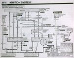
Power Distribution 050.jpg


miesk5

96 Bronco 5.0
Staff member
Moderator
Joined
Oct 18, 2005
Messages
9,071
Reaction score
1,019
Location
Floating in the Pacific
yo,

The PIP wire insul. thAng could give DTC 211 as described in;

TSB 95-15-11 Hesitation, Stumble, Stall, Miss, No Start, No Spark by Ford via Chilton

HESITATION/STUMBLE—INTERMITTENT—4.9L, 5.0L, 5.8L AND 7.5L ENGINES

MISS—INTERMITTENT—4.9L, 5.0L, 5.8L AND 7.5L ENGINES

NO START/NO SPARK—INTERMITTENT—4.9L, 5.0L, 5.8L AND 7.5L ENGINES

STALL—INTERMITTENT—4.9L, 5.0L, 5.8L AND 7.5L ENGINES

ISSUE:

Vehicles may exhibit various driveability symptoms, such as no start, no spark, hesitation/stumble/stall/miss and/or Diagnostic Trouble Code (DTC) 211. The symptoms may occur during any drive mode or at idle. These concerns may be caused by the shielding drain wire (Circuit 48.) cutting through the insulation of, and shorting to, the Profile Ignition Pickup (PIP) wire (Circuit 395) or the spark output (SPOUT) wire (Circuit 929) near the Powertrain Control Module (PCM) 60-pin connector. A protruding wire from Splice 145 may also cause the same concern as the wire strand shorts to the PIP, SPOUT, or the foil wrap surrounding the drain wire.

ACTION:

Inspect PIP - Circuit 395 (GY/O), Ignition Ground (IGN GND) - Circuit 259 (O/R), and SPOUT - Circuit 929 (PK) for possible cut insulation from Circuit 48. Also, inspect Splice 145 - Circuit 395 (GY/O) for stray wire strands. If wire insulation is cut, exposing copper wire, repair cut insulation with 3M Mastic Tape. Refer to the following procedure for service details.

SERVICE PROCEDURE

1. Disconnect battery ground cable.

2. If vehicle has the speed control option, remove the speed control servo bracket and position it out of the way for improved access.

3. Disconnect the connector at the Ignition Control Module (ICM - formerly TFI).

4. Unbolt the 60-pin connector from the PCM and pull the wiring up to work on.

5. Remove the 1" (25.4mm) diameter convoluted tubing from the wiring assembly. The date code tag will remain taped to the convoluted tubing.

6. Remove/cut the tape of the wiring assembly. Work toward the the ICM connector (pull back convoluted tubing as needed).

7. Unravel aluminum foil tape and electrical drain wire (Circuit 48.) from main bundle, exposing the junction or "Y" splice between the ICM tapeout and the PCM tapeout. Be careful with the foil wrap because it will be reused.

NOTE: THE FOIL WRAP LENGTH WILL BE ABOUT 5" (127mm) BEYOND THE "Y" BRANCH. THE END WILL BE TOWARD THE ICM CONNECTOR.

8. After the foil wrap is removed, look for the three (3) "grouped" wires in question at the "Y" splice. The three (3) wires are: PIP - Circuit 395 (GY/O), IGN GND - Circuit 259 (O/R), and SPOUT - Circuit 929 (PK).

9. Locate the (bare) electrical drain wire. Wire end is toward the ICM connector, again, about 5" (127mm) from the "Y" splice. Unravel wire from the top (ICM) end and down to the area where the bare wire makes contact with the three (3) wires mentioned above.

10. Inspect for any damage to the insulation of the three (3) wires in question. If wire insulation is cut, exposing copper wire, repair cut insulation with 3M Electrical Moisture Sealant-Mastic Tape (3M Part No. 054007-06147).

11. Inspect Splice 145 - Circuit 395 (GY/O) for stray wire strands (Figure 3). If stray wire is found, apply pressure on the wire with pliers to bend the wire down and wrap the splice with three (3) layers of flame retardant vinyl tape, or equivalent, to ensure the wire does not make contact with other wires or the foil wrap.

12. Carefully rewrap the bare electrical drain wire and foil. Work backward, toward the ICM connector end. Tape end of foil wrap to secure.

13. Retape worked area securely (between PCM and ICM connectors) with flame retardant vinyl tape, or equivalent.

14. Reinstall all convoluted tubing and tape ends of tubing to the tubing with flame retardant vinyl tape, or equivalent.

15. Reinstall PCM connector to the PCM.

16. Reinstall the ICM connector.

17. Reinstall the speed control servo bracket (two bolts) if applicable, and tighten bolts to 15-18 N-m (11-13 lb-ft).

18. Reconnect battery ground cable.

SEE DIAGRAMS


miesk5

96 Bronco 5.0
Staff member
Moderator
Joined
Oct 18, 2005
Messages
9,071
Reaction score
1,019
Location
Floating in the Pacific
yo,

and More on TSB 95-15-11

Intermittent No-Spark: Spark w/SPOUT Connector Un-Plugged, but Falter and/or No-Spark w/SPOUT Connected (similar to Hesitation, Stumble, Stall, Miss, No Start, No Spark); "It seems that the insulation around many PIP sensors breaks down prematurely - a condition that leads to shorting of the wires leading to the TFI ignition module. I always replace a PIP sensor along with a defective ignition module, if it has "soft" insulation...This month's column is about a Ford Ranger one of my students (Drew) said "would only run for about a mile, then die." Since we were in the middle of our electrical and engine performance unit, this vehicle would serve as a perfect troubleshooting opportunity. The story from my student went as follows: The vehicle began stalling intermittently during driving, but would usually restart right away. Sometimes, however, it would have to sit for a few minutes. Drew had replaced the ignition coil on the advice of a family friend, but the problem persisted. Next, the thick film ignition (TFI) module was replaced with a quality no-name brand from a local parts house. The stalling condition continued. Now, Drew had spent enough time with his friend to decide that the next logical course of action was to replace the entire distributor. This is where I became involved. As soon as I heard three ignition components had been replaced with no cure, I just had to mutter, "Sure, bring it in tomorrow!" The next day, I took the time to discuss with my students the proper method by which to approach this customer concern. Logical Troubleshooting Figure 1 - This is the old profile ignition pickup (PIP) sensor with defective insulation. Figure 2 - Believe it or not...Here's the original distributor with silicone around the cap sealing surface. Figure 3 - Here's the old distributor next to the new one, with the transferred ignition module. Figure 4 - New ignition coil. Figure 5 - Both the old and new spark plugs. Figure 6 - The root cause of the problem, which is the shielding wire grounding out the SPOUT signal. Troubleshooting is the process of testing a system to determine and isolate a malfunction. An automotive technician is often involved in troubleshooting a malfunctioning system on a car, such as this Ford TFI-IV ignition system. Skilled automotive techs do more than just troubleshoot - they logically troubleshoot. I tell my students they must approach this diagnosis just as a master technician would, by following a known, good, logical procedure that will isolate the root cause of the customer concern in a timely manner. The sequence I teach is: Verify the customer concern. Perform a thorough visual inspection. Test for the cause of the concern and perform published system testing. Isolate the root cause and perform the repair. Verify the repair. This is based on General Motor's Strategy-Based Diagnostics and I stress this to my students repeatedly. TSBs Drew found three technical service bulletins (TSBs) pertaining to the ignition system: TFI STALL NO START - TFI MODULE DIAGNOSIS AND SEALING: This bulletin addresses loss of module ground due to salt and moisture entering a module mounting *****. TFI ENGINE NO START/STALL AT IDLE - NEW IGNITION MODULE: This TSB talks about an internal short-circuit in some model TFI modules. DRIVEABILITY CONCERNS - MOIST EEC-IV CONNECTORS: This bulletin asks the tech to check for unsealed EEC-IV connectors and check for moisture or corrosion. Verifying the Concern, Performing the Visual Popping the hood on the Ranger revealed the new coil, new distributor cap and new TFI module screwed to the side of the distributor housing. The engine would only run for a few minutes before dying, just as though the key had been turned off. Sure enough, no spark occurred at spark testers when the no-start was present. Based on the TSB information, I directed Drew to inspect all of the EEC connectors and perform a complete inspection of all pertinent wires and components. We did notice that many of the wiring harnesses had some oil and road grime, and that there was some peeling of the wiring insulation at the EEC-IV module connector, although none of the wires appeared to be shorting. Now, Drew had already purchased a rebuilt distributor and plopped it down on our workbench. At this point I told Drew about a preliminary test that I learned to determine if the profile ignition pickup (PIP) sensor might be defective. We popped the cap and I pushed my fingernail down into the soft, gooey insulation surrounding the PIP sensor. This has historically been a red flag for techs hunting an ignition fault on Ford vehicles equipped with TFI ignition systems. It seems that the insulation around many PIP sensors breaks down prematurely - a condition that leads to shorting of the wires leading to the TFI ignition module. I always replace a PIP sensor along with a defective ignition module, if it has "soft" insulation. I liken this to replacing a high energy ignition (HEI) module in an older Delco-Remy distributor. Is it prudent to replace the ignition pickup coil while you're inside this distributor? I always let the customer make the decision, but I lobby for replacement. Drew was adamant about replacing the distributor, so I helped him through the process of marking the rotor and the housing, then swapping the TFI module from the old distributor to the new one. With this distributor installed, the Ranger now had a new ignition coil, ignition module, cap, rotor and PIP sensor. You can guess what happens next; the stalling condition is still present! Testing for the Root Cause At this point I had Drew's full attention, so we systematically walked through a proper diagnosis. A TFI testing worksheet showed a simple and systematic process that eliminates suspect parts and circuits, one-by-one, until the cause for the concern is discovered. The only problem, I explained, was that the engine would usually start right back up, and that made many of the tests ineffective. Still, we verified proper voltages at the coil, resistance across the coil and ground for the distributor. PIP Signal I decided to hook my lab scope up to the PIP and spark output (SPOUT) wires to isolate exactly where I was losing my signal to trigger the coil. The PIP signal is generated in the PIP assembly and is an indication of crankshaft position and speed. The PIP signal is fed to both the TFI module and the PCM. Hooking up to this signal with my lab scope would verify the entire distributor assembly. When the engine died and spark disappeared, the square wave produced by the PIP remained intact. SPOUT Signal The PIP signal is one of the many inputs processed by the PCM. After receiving all of its sensor inputs, the PCM produces a new signal called the SPOUT. The spark output signal represents the engine operating condition "electronically" and is sent back to the TFI module for comparison with the PIP signal. The TFI module then uses both of these signals to fire the coil at the proper timing interval. While watching the SPOUT signal on my scope, the square wave became jagged and jumpy as the engine sputtered, and then became a flat line before the engine died. Now we had a suspect - the PCM. A Break I noticed that when I unplugged the SPOUT connector to check base timing, and let the engine run at base timing, it never died. Unfortunately, this pointed me back to the PCM as a possible cause of my fault. But, when I plugged the SPOUT connector back together, I could make the engine falter and die by gently twisting the harness. Yes! I was sure I had located the fault, and I was right. Look at the figure with the yellow spark output signal wire that is without a section of insulation. This section happens to run through a shield ground that provided a convenient ground source for the SPOUT signal. Just the right bump in the road or vibration from the engine would provide a path of lesser resistance for the SPOUT signal, killing the coil trigger..."; etc. (for a Ranger, but similar); Note, site won't allow you to return to this page, so open URL in a new Window; SEE Hesitation, Stumble, Stall, Miss, No Start, No Spark and/or DTC 211, TSB 95-15-11 for 93-95 (Shorts in Profile Ignition Pickup (PIP) & Spark Output (SPOUT) by Ford via CHILTON; from Ford EVTM; The Control Module (PCM) runs the pump{s} for one second when it receives an ignition- on signal. It also runs the pumps as long as it receives a PTP signal from the Hall-effect devices, it continues pump operation even after the key is released from START. If the PTP signals fall below 120RPM, the control module cuts off the signal to the fuel pump relay or the integrated relay control module. The pump will also run when the terminals of the fuel pump test connector are jumped. the Control module signals the pump when it receives a CRANK signal, and when the Control module gets PIP signals that the engine is running. the pump does not run if the PIP indicates the engine is not running even with ignition ON {except for that first one second}.

Source: by Brian M at asashop.org

or,

Misfiring, Rough Idle, Surge, & Ping-Knock Symptoms, due to a Magnetized Shutter Wheel, (Bronco & all Fords w/EEC IV & TFI);"...Inside the TFI distributor is a Hall-Effect sensor that provides an RPM and POSITION signal to the Ignition module and ECM for fuel and ignition control. Mounted to the distributor shaft is a "shutter-wheel" that passes through the Hall-Effect sensor. The slots or windows cut in the shutter-wheel are what makes the Hall-Effect sensor switch on/off to create the signal it sends out. The shutter-wheel is supposed to be a piece of "dead" steel but can become magnetized. A magnetized wheel can cause very erratic operation of the Hall-Effect and resulting erratic output signal. The Test: There are a couple of ways to check for this condition. One is to simply pull off the distributor cap and see if something steel will "stick" to the shutter-wheel. Make sure that whatever you are using to check the wheel with isn't magnetized itself. A more accurate method would be to watch the wave-form on the "SPOUT" wire with a Vantage or Lab-Scope. The SPOUT is the wire with the connector in it that you unplug to set ignition timing. Monitor the wave-pattern on the SPOUT with the timing-connector in. If there is anything erratic about the wave-form, unplug the timing connector and re-check the wave-form. If the pattern "cleans up" all of a sudden, chances are good that you have a magnetized shutter-wheel. The Fix: Most shutter-wheels can be removed from the distributor shaft with a couple of screws. Everybody seems to have their own way of de-magnetizing the wheels but good success has been had with bulk audio-tape erasers or by placing the wheel in an engine parts cleaning oven and baking it. That last one sounds weird but it works..." Scroll down

Source: by snapon.com via archive.org

==========


Members online

No members online now.

Latest posts

Forum statistics

Threads
22,521
Messages
135,985
Members
25,125
Latest member
ReturnToHangar
Top