Yo,
I see no electrical correlation between taillights and instrument panel lights not working.
For exterior lights, check the lamps and their sockets for corrosion etc.
Here are Ford's pin-point tests. I chose the stop lamps and markers for now.
Are exterior turn signal lights working?
PINPOINT TEST F: STOPLAMPS/HI-MOUNT STOPLAMPS INOPERATIVE
Multi-Function ( turn, flash to pass) Switch Continuity Test
Refer to these diagnostic charts to resolve concerns with brake lights:
MULTI-FUNCTION SWITCH CONTINUITY TEST, F-SERIES, BRONCO
To Test
Connect Self-Powered Test Light or Ohmmeter to Terminals
Move Switch to These Positions
A Good Switch Will Indicate
Flash-to-Pass
196 (DB/O) and 12 (LG/BK)
15 (R/Y) and 13 (R/BK)
Pull and hold lever stalk toward steering wheel
Closed circuit
Dimmer HI Beam
15 (R/Y) and 12 (LG/BK)
Lever stalk away from steering wheel
Closed circuit
Dimmer LO Beam
15 (R/Y) and 13 (R/BK)
Lever stalk in detent closest to steering wheel
Closed circuit
Turn Switch Circuit
44 (LB) and 9 (LG/O)
44 (LB) and 3 (LG/W)
Turn switch to TURN LEFT and hazard switch to OFF
Closed circuit
Turn Switch Circuit
44 (LB) and 5 (O/LB)
44 (LB) and 2 (W/LB)
Turn switch to TURN RIGHT and hazard switch to OFF
Closed circuit
Hazard Switch
385 (W/R) and 2 (W/LB),
5 (O/LB), 3 (LG/W), 9 (LG/O)
Hazard switch on (button depressed), then released to FULL OUT position)
Closed circuit
Stoplamp Feed-Through Circuit
511 (LG) and 9 (LG/O)
511 (LG) and 5 (O/LB)
Turn switch to center (no turn) and hazard switch to OFF
Closed circuit
Washer Switch Circuit
590 (DB/W) and 993 (BR/W)
With wiper switch off, push washer switch in; release washer switch
Closed circuit
103.3k ohm
Wiper Switch Circuit
589 (O) and 993 (BR/W)
Off
Int
Lo
Hi
47.6k ohm ± 5%
11.33k ohm ± 5%
4.08k ohm ± 5%
Closed circuit
Interval Time Adjust
590 (DB/W) and 993 (BR/W)
Int and Off
Rotate control toward OFF; ohmmeter will show smoothly increasing resistance from 3.3k ohm min. to 103.3k ohm max.
(± 10%)
Lo and Hi
3.3k ohm 10%
F1 CHECK SUPPLY TO STOPLAMPS
- With Rotunda 73 Digital Multimeter 105-R0051 or equivalent connected to a known good ground, check for voltage on Circuit 10 (LG/R) at stoplight switch.
Is battery voltage present?
Yes
No
GO to
F4.
GO to
F2.
Stoplamps, Bronco

F2 CHECK SUPPLY CIRCUIT TO STOPLIGHT SWITCH
- Using Rotunda 73 Digital Multimeter 105-R0051 or equivalent connected to a known good ground, check Circuit 383 (R/W)/10 (LG/R) at output side of I/P fuse panel fuse 13.
Is battery voltage present?
Yes
No
REPLACE fuse or SERVICE Circuit 383 (R/W)/10 (LG/R) for open circuit. RESTORE vehicle. RETEST system.
GO to
F3.
F3 CHECK CIRCUIT 383 (R/W)/10 (LG/R) FOR SHORT
- Remove IP fuse panel fuse 13.
- Using Rotunda 73 Digital Multimeter 105-R0051 or equivalent connected to a known good ground, connect second lead to output side of IP fuse panel fuse 13.
- Measure resistance.
Is resistance 5 ohms or less?
Yes
No
SERVICE Circuit 383 (R/W)/10 (LG/R) for short to ground. RESTORE vehicle. RETEST system.
REPLACE damaged fuse. RESTORE vehicle. RETEST system.
F4 CHECK STOPLIGHT SWITCH OUTPUT
- Depress stoplight switch and hold.
- Using a voltmeter connected to a known good ground, check Circuit 511 (LG) at stoplight switch.
Is battery voltage present?
Yes
No
GO to
F5.
REPLACE damaged stoplight switch. RESTORE vehicle. RETEST system.
F5 CHECK STOPLIGHT SWITCH INPUT TO MULTI-FUNCTION SWITCH
- Gain access to the multi-function switch. With Rotunda 73 Digital Multimeter 105-R0051 or equivalent connected to a known good ground, connect other end to Pin C1-9, Circuit 511 (LG) at the multi-function switch connector.
- Apply brake pedal, and hold.
Is battery voltage present?
Yes
No
GO to
F6.
SERVICE Circuit 511 (LG) for an open. RESTORE vehicle. RETEST system.
F6 CHECK MULTI-FUNCTION SWITCH OUTPUT TO STOPLAMPS
- Using Rotunda 73 Digital Multimeter 105-R0051 or equivalent connected to a known good ground, and brake pedal still applied, check Circuit 9 (LG/O) at Pin C1-10 of multi-function switch connector, or Circuit 5 (O/LB) at Pin C1-2 of multi-function switch connector.
Is battery voltage present?
Yes
No
LEAVE brake pedal applied. GO to
F7.
REPLACE damaged multi-function switch. RESTORE vehicle. RETEST system.
F7 CHECK STOPLAMP SUPPLY AT BULB
- Gain access to either stoplamp connector. Disconnect stoplamp connector.
- Using Rotunda 73 Digital Multimeter 105-R0051 or equivalent connected to a known good ground, check Circuit 9 (LG/O) and Circuit 5 (O/LB) for voltage.
Is battery voltage present?
Yes
No
GO to
F8.
SERVICE Circuit 9 (LG/O) or Circuit 5 (O/LB) for open circuit. RESTORE vehicle. RETEST system.
F8 CHECK STOPLAMPS GROUND
- Unapply brake pedal.
- Using Rotunda 73 Digital Multimeter 105-R0051 or equivalent connected to a known good ground, connect second lead to Circuit 57 (BK) at either stoplamp bulb connector.
- Measure resistance.
Is resistance 5 ohms or less?
Yes
No
REPLACE damaged miniature bulb. RESTORE vehicle. RETEST system. GO to
F9.
SERVICE Circuit 57 (BK) for open circuit. RESTORE vehicle. RETEST system.
■
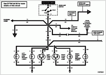
PINPOINT TEST R: PARKING LAMPS INOPERATIVE
Turn Signal and Marker Lamps, F-Series and Bronco

R1 CHECK CIRCUIT 14 (BR) AT HEADLAMP SWITCH
- Actuate headlamp switch to the PARK position.
- Using Rotunda 73 Digital Multimeter 105-R0051 or equivalent connected to a known good ground, check Circuit 14 (BR) at headlamp switch Pin R for voltage.
Is battery voltage present?
Yes
No
SERVICE Circuit 14 (BR) for an open circuit. RESTORE vehicle. RETEST system.
GO to
R2.
R2 CHECK SUPPLY TO PARKING LAMPS
- With Rotunda 73 Digital Multimeter 105-R0051 or equivalent, check for voltage on Circuit 195 (T/W) at headlamp switch.
Is battery voltage present?
Yes
No
REPLACE damaged headlamp switch. RESTORE vehicle. RETEST system.
GO to
R3.
R3 CHECK SUPPLY CIRCUIT TO HEADLAMP SWITCH
- Using Rotunda 73 Digital Multimeter 105-R0051 or equivalent connected to a known good ground, check Circuit 195 (T/W) at output side of IP fuse 4 (15A).
Is battery voltage present?
Yes
No
SERVICE Circuit 195 (T/W) for an open circuit. RESTORE vehicle. RETEST system.
GO to
R4.
R4 CHECK IP FUSE 4
- Remove and inspect IP fuse panel fuse 4, 15A for an open circuit.
Is fuse 4 good?
Yes
No
GO to
R5.
REPLACE fuse 4. REPEAT step
R4.
R5 CHECK SUPPLY TO FUSE 4
- Using a Rotunda 73 Digital Multimeter 105-R0051 or equivalent, check for voltage at feed side of IP fuse 4, Circuit 38 (BK/O) and load side of power distribution box fuse 20, 50A, Circuit 38 (BK/O).
Is battery voltage present?
Yes
No
GO to
R6.
REPAIR open in Circuit 38 (BK/O). RESTORE vehicle. RETEST system.
R6 CHECK POWER DISTRIBUTION BOX FUSE 20
- Remove and inspect power distribution box fuse 20, 50A for an open circuit.
Is fuse 20 good?
Yes
No
REPAIR power distribution box power feed, Circuit 37 (Y). RESTORE vehicle. RETEST system.
REPLACE fuse 20, 50A. RESTORE vehicle. RETEST system.
●■●
INSTRUMENT PANEL LIGHTS:
Instrument Cluster and Panel Illumination, Except Motorhome
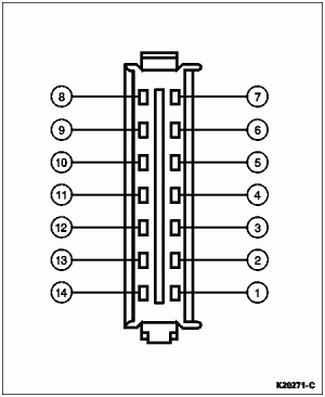
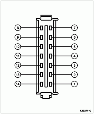
 Instrument Cluster Connector C1

Pin Number
Circuit
Circuit Function
1
904 (LG/R)
Charge Indicator Lamp
2
932 (GY/W)
High Beam Indicator Lamp Feed
12 (LG/BK)
High Beam Indicator*
3
57 (BK)
Ground
4
450 (DG/LG)
Seat Belt Warning Indicator Lamp Feed
5
29 (Y/W)
Fuel Level Input (with Tachometer)
6
19 (LB/R)
Instrument Cluster Illumination Input
7
57 (BK)
Ground
8
2 (W/LB)
Front Turn Signal Lamp (RH)
9
648 (W/PK)
Tachometer Input Signal
11 (T/Y)
Tachometer Input Signal*
10
398 (BK/Y)
Tachometer Ground (Eight-Cylinder Gasoline Only)
57 (BK)
Tachometer Ground*
11
784 (LB/BK)
Low Range Indicator Input
—
Not Used*
12
210 (LB)
4x4 Indicator Lamp to Switch
608 (BK/Y)
Door Ajar Input*
13
640 (R/Y)
Power (Hot in START or RUN)
14
16 (R/LG)
Charge Indicator Input
* Motorhome only.
Instrument Cluster Connector C2

Pin Number
Circuit
Circuit Function
1
875 (BK/LB)
Unique Ground to Gauges
2
658 (PK/LG)
PCM to Check Engine Indicator Lamp
3
603 (DG)
Failure Warning Light (ABS)
4
977 (P/W)
Brake Warning Indicator Input
5
—
Not Used
6
29 (Y/W)
Fuel Level Input (Without Tachometer)
7
3 (LG/W)
Front Turn Signal Lamp (LH)
8
31 (W/R)
Oil Pressure Indicator to Oil Pressure Sending Unit
9
875 (BK/LB)
Unique Ground to Gauges (F-Series)
570 (BK/W)
Dedicated Ground to Gauges (Bronco)
10
39 (R/W)
Temperature Gauge to Temperature Sending Unit
11
531 (DG/Y)
Brake Level Switch Input
12
608 (BK/Y)
Air Bag Warning Lamp
13
640 (R/Y)
Power (Hot in START or RUN)
14
—
Not Used

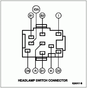
Pin Number
Circuit
Circuit Function
B1
38 (BK/O)
Power (Hot at All Times)
IGN
137 (Y/BK)
Power (Hot in ACC or RUN)
—
Not Used*
B2
195 (T/W)
Power (Hot at All Times)
I
294 (W/LB)
From Headlamp Switch to Fuse
19 (LB/R)
Instrument Panel Lamp Feed*
D2
706 (GY)
To Remote Keyless Entry
55 (BK/PK)
Courtesy Lamp Switch to Courtesy Lamp (Without Remote Keyless Entry)
53 (BK/LB)
Interior Lamp Switch Ground Feed*
H
15 (R/Y)
Headlamp Dimmer Switch Feed
D1
54 (LG/Y)
Interior Lamp Switch Feed
57 (BK)
Interior Lamp Switch Ground*
R
14 (BR)
Exterior Lamps Feed
DN
484 (O/BK)
Radio Liquid Crystal Display Feed
—
Not Used*
PINPOINT TEST

INSTRUMENT CLUSTER ILLUMINATION INOPERATIVE
C1 CHECK BATTERY VOLTAGE SUPPLY
- Pull headlamp switch into PARK position.
- Rotate headlamp switch **** and shaft fully clockwise without turning on courtesy lamps.
- Measure voltage with Rotunda 73 Digital Multimeter 105-R0051 or equivalent Circuit 19 (LB/R) at IP fuse panel.
Is battery voltage present?
Yes
No
TURN headlamp switch to OFF position. GO to
C3.
GO to
C2.
C2 MEASURE VOLTAGE
- Measure voltage at feed side of instrument panel fuse.
Is battery voltage present?
Yes
No
REPLACE fuse. RESTORE vehicle. RETEST system.
SERVICE open or ground short in IP fuse panel battery feed. RESTORE vehicle. RETEST system.
C3 CHECK CIRCUIT 19 (LB/R)
- Disconnect instrument cluster connector C1.
- Check resistance of Circuit 19 (LB/R) with Rotunda 73 Digital Multimeter 105-R0051 or equivalent between instrument cluster connector C1 and instrument panel fuse.
Is continuity present?
Yes
No
GO to
C4.
SERVICE open in Circuit 19 (LB/R). RESTORE vehicle. RETEST system.
C4 CHECK INSTRUMENT CLUSTER GROUND
- Disconnect instrument cluster connector C1.
- Test continuity to ground at Circuit 57 (BK) at connector C1.
Is continuity OK?
Yes
No
REPLACE instrument cluster printed circuit. RESTORE vehicle. RETEST system.
REPAIR open in Circuit 57 (BK). RESTORE vehicle. RETEST system.


