Yo brainybroncoboy,
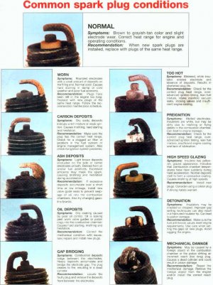
Pull more plugs.

Intake Manifold Vacuum TestBring the engine (6007) to normal operating temperature. Connect Rotunda Vacuum/Pressure Tester 164-R0253 or equivalent to the intake manifold (9424). Run the engine at the specified idle speed.
The vacuum gauge should read between -51 and -74 kPa (15 and 22 in-Hg) depending upon the engine condition and the altitude at which the test is performed. SUBTRACT 5.5 kPa FOR EVERY 500 METERS ABOVE SEA LEVEL. SUBTRACT ONE INCH FROM THE SPECIFIED READING FOR EVERY 1,000 FEET OF ELEVATION ABOVE SEA LEVEL.
The reading should be quite steady. It may be necessary to adjust the gauge damper control (where used) if the needle is fluttering rapidly. Adjust damper until needle moves easily without excessive flutter.
Vacuum Gauge Readings, Interpretation
A careful study of the vacuum gauge reading while the engine is idling will help pinpoint trouble areas. Always conduct other appropriate tests before arriving at a final diagnostic decision. Remember that vacuum gauge readings must be interpreted with care.
Most vacuum gauges have a "normal" band indicated on the gauge face.
Following are potential gauge readings. Some should be considered as normal; others should be investigated further.

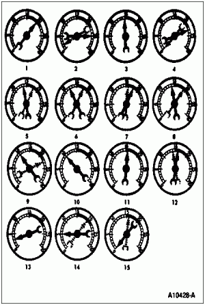
- NORMAL READING: Needle between -51 and -74 kPa (15 and 22 in-Hg) and holding steady.
- NORMAL READING DURING RAPID ACCELERATION AND DECELERATION: When engine is rapidly accelerated (dotted needle), needle will drop to a low (not to zero) reading. When throttle is suddenly released, the needle will snap back up to a higher than normal figure.
- NORMAL FOR HIGH LIFT CAM WITH LARGE OVERLAP: Needle will register as low as -51 kPa (15 in-Hg) but will be relatively steady. Some oscillation is normal.
- WORN RINGS OR DILUTED OIL: When engine is accelerated (dotted needle), needle drops to 0 kPa (zero in-Hg). Upon deceleration, needle runs slightly above 74 kPa (4 in-Hg).
- STICKING VALVE(S): When the needle (dotted) remains steady at a normal vacuum but occasionally flicks (sharp, fast movement) down and back about 13 kPa (4 in-Hg), one or more valves may be sticking.
- BURNED OR WARPED VALVES: A regular, evenly spaced, downscale flicking of the needle indicates one or more burned or warped valves. Insufficient hydraulic lash adjuster clearance will also cause this action.
- POOR VALVE SEATING: A small but regular downscale flicking can mean one or more valves are not seating.
- WORN VALVE GUIDES: When the needle oscillates (swings back and forth) over a 13 kPa (4 in-Hg) range at idle speed, the valve guides (6510) could be worn. As engine speed is increased, the needle will become steady if the guides are responsible.
- WEAK VALVE SPRINGS: When the needle oscillation becomes more violent as engine rpm is increased, weak valve springs (6513) are indicated. The reading at idle could be relatively steady.
- LATE VALVE TIMING: A steady but low reading could be caused by late valve timing.
- IGNITION TIMING RETARDING: ******** ignition timing will produce a steady but low reading.
- INSUFFICIENT SPARK PLUG GAP: When spark plugs (12405) are gapped too close, a regular, small pulsation of the needle can occur.
- INTAKE LEAK: A low, steady reading can be caused by an intake manifold or throttle body gasket (TB gasket) (9E936) leak.
- BLOWN HEAD GASKET: A regular drop of approximately 33-50 kPa (10-15 in-Hg) can be caused by a blown head gasket (6051) or warped head-to-block mounting surface.
- RESTRICTED EXHAUST SYSTEM: When the engine is first started and is idled, the reading may be normal. As the engine rpm is increased, the back-pressure caused by a clogged muffler, kinked tail pipe, etc., will cause the needle to slowly drop to zero. The needle then may slowly rise. Excessive exhaust clogging will cause the needle to drop to a low point even if the engine is only idled.
When vacuum leaks are indicated, search out and correct the condition. Excess air leaking into the system will upset the fuel mixture and cause conditions such as rough idle, missing on acceleration, or burned valves. If the leak exists in an accessory unit, such as the power brake, the unit will not function correctly. ALWAYS SERVICE VACUUM LEAKS.
Oil Consumption Test
Use the following procedure to find the source of excessive internal oil consumption.
- Determine what the customer considers excessive oil consumption to be. Note vehicle mileage and the following observations:
How many miles are typically driven per quart of oil used?
- How is the vehicle being used (e.g., sustained high speed operation, heavy loads, trailer towing, high ambient temperature, etc.)?
- What does the customer expect normal oil consumption to be?
- Verify that the engine has no external oil leak as described under Engine Oil Leaks in the Service Procedures portion of this section.
- Verify that the engine has the proper oil level dipstick (6750) by comparing the part number stamped on it against the Ford Master Parts Catalog. Verify that the oil level dipstick and oil level indicator tube (6754) are unmodified and in good condition. Verify that the oil level indicator tube is properly seated in the block or oil pan, and the dipstick seats properly in the oil level indicator tube.
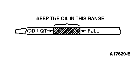
- Verify that the engine is not being run in an overfilled condition. Check the oil level at least five minutes after a hot shutdown with the vehicle parked in a level area. Under no circumstances should the oil level be above the letter F in the word FULL. If a significant overfill is indicated, perform Steps 5a through 5d to verify the dipstick calibration. If the dipstick calibration checks OK, instruct the customer to avoid overfilling the engine and return the vehicle to service. To verify the vehicle's actual oil consumption, perform Steps 5e and 5f only after the oil level dipstick has been calibrated.

- Perform engine oil consumption test as follows:
Drain engine oil. Remove and replace oil filter. Using 0.9L (1 quart) less than recommended, refill crankcase with recommended quality of oil.
- Run the engine for three minutes (ten minutes if cold), then turn engine off. Allow oil to drain into the oil pan for an additional five minutes (vehicle should be on level ground).
- Remove oil dipstick and wipe clean. Do not wipe with anything contaminated with silicone compounds. Reinstall dipstick being sure to seat the dipstick firmly in the oil level indicator tube. Remove the dipstick and scribe a mark on the back (unmarked) surface at the indicated oil level. This should be about the same level as the ADD mark on the face of the dipstick.
- Add 0.9L (1 quart) of oil. Restart the engine and allow it to idle for at least two minutes. Shut down and allow oil to drain back for at least five minutes. Mark the dipstick using the procedure above. This level may range from slightly below the top of the crosshatched area to slightly below the letter F in FULL.
- Instruct the customer to drive the vehicle as usual and perform the following steps:
- Check the oil level regularly at intervals of 161 to 241 km (100 to 150 miles).
- Return to the service facility when the oil level drops below the lower (ADD) mark scribed on the dipstick by the technician.
- In an emergency, add only full litres (quarts) of the same oil and note the mileage at which the oil was added.
- Check the oil level under the same conditions as in Steps 5c and 5d, reading the back of the oil level dipstick where the scribe marks are located.
- Measure the distance from the oil level to the upper scribe mark on the oil level dipstick and record.
- Measure the distance between the two scribe marks and record.
- Divide the first measurement by the second. Add one to this total for every quart added by the customer as instructed in Step 5e.
- Divide the distance driven during the oil test by the result. This quantity is the approximate oil consumption rate in miles per quart (MPQ).
- If the calculated oil consumption rate is unacceptable, proceed to Step 6.
- Check PCV valve system. Make sure system is not plugged.
- Check for plugged oil drain-back holes in cylinder heads (6049) and cylinder block (6010).
- If condition still exists, perform a cylinder compression test as described in this section, and/or perform a cylinder leak detection test with Rotunda Pressurization Kit 014-00705 or equivalent. This can be helpful in determining source of oil consumption, i.e., valves, piston rings, etc.
- Check valve guides (6510) for excessive guide clearance. Replace all valve stem/guide seals after correct valve guide clearance has been verified.
- NOTE: After checking for worn parts, if it is determined parts should be replaced, make sure correct replacement parts are used.
Worn or damaged internal engine components can cause excessive oil consumption. Small deposits of oil on tip of spark plugs (12405) can be a clue to internal oil consumption. If internal oil consumption still persists, proceed as follows:
Remove engine from vehicle and place it on an engine work stand. Remove intake manifold(s), cylinder heads, oil pan (6675) and oil pump (6600). Refer to Section 03-01A (4.9L SFI), Section 03-01B (5.0L and 5.8L MFI), Section 03-01C (7.5L MFI) or Section 03-01D (7.3L diesel).
- Check piston ring clearance, ring gap and ring orientation as outlined in this section. Service as required.
- Check for excessive bearing clearance as outlined in this section. Service as required.
- Perform Step 5 again to confirm oil consumption concern has been resolved.
Oil Pressure Test
SPECIAL SERVICE TOOL(S) REQUIRED Description Tool Number Engine Oil Pressure Gauge T73L-6600-A
- Disconnect and remove the oil pressure sensor (9278) from the engine.
- Connect an Engine Oil Pressure Gauge T73L-6600-A and Transmission Test Adapter D87C-77000-A, or equivalent, to the oil pressure sender ***** port.
- Run the engine until normal operating temperature is reached.
- Run the engine at 3,000 rpm and record the gauge reading.
- The oil pressure should be: 392-490 kPa (57-71 psi) at 3,000 rpm.
- If the pressure is not within specification, check the following possible sources:
- Insufficient oil
- Oil leakage
- Worn or damaged oil pump
- Clogged oil pump screen cover and tube (6622)
- Excessive main bearing clearance
- Excessive connecting rod bearing clearance


