Running diagnostics for fuel pump primer not shutting off...

Disclaimer: Links on this page pointing to Amazon, eBay and other sites may include affiliate code. If you click them and make a purchase, we may earn a small commission.

griff

Member
Joined
Jun 25, 2010
Messages
45
Reaction score
22
Location
Chicagoland
Saw the other thread about this. Mine is a bit different in symptoms.

1992 Bronco, 5.8L.

I have new battery showing 12.5 volts, alternator showing 14+ volts while running, new fuel pump relay installed, ground by battery secure/no corrosion.

Car can start when I hear the primer finish (usually 3-5 sec). Will not start due to primer noise in rear signaling stuck on/open.

Frustrating because I am needing to buy lumber for a job before cold weather sets in.

Do I need to be making plans to get a new fuel pump? Or is there another check to see if I can avoid it?

Thanks,

griff
 

Motech

Well-known member
Joined
Jun 21, 2021
Messages
494
Reaction score
585
Location
Santa Cruz, CA:
Pump staying on with key off? If so, that's almost always a sticking relay, as you've already dealt with.

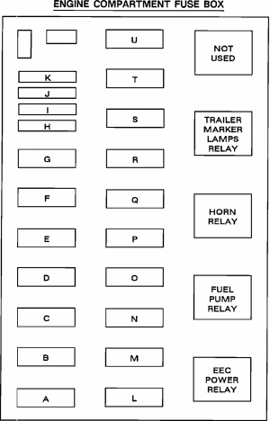
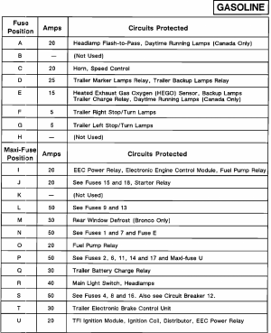
I would make sure you replaced the correct relay. Fuel Pump and EEC Power Relay live next to each other, are interchangeable, and without clear markings on the junction box, I've made that mistake myself.

download (1).png

download (2).png
 

Motech

Well-known member
Joined
Jun 21, 2021
Messages
494
Reaction score
585
Location
Santa Cruz, CA:
A quick and simple test is to tap on the fuel pump relay with a screwdriver handle while the pump is running with the key off. If it shuts off, there it is.

The truck not starting while this is happening is curious though. It's possible that voltage supplied through a sticking relay is quite a bit lower at the pump then when it's fully engaged by the PCM.
 
OP
OP
griff

griff

Member
Joined
Jun 25, 2010
Messages
45
Reaction score
22
Location
Chicagoland
A quick and simple test is to tap on the fuel pump relay with a screwdriver handle while the pump is running with the key off. If it shuts off, there it is.

The truck not starting while this is happening is curious though. It's possible that voltage supplied through a sticking relay is quite a bit lower at the pump then when it's fully engaged by the PCM.
Thx for chiming in Motech! I did place the fuel pump relay in the right space. I even replaced it with the old one after it didn't help. Checked all the fuses.

I checked all the grounds and made sure they were solid/clean. I could not pull any codes with my OBD I Ford scanner. Just sat at 000 without any indicators that it was connected.

The primer stays on only with the key turned. However, it will not shut-off until the key is returned to pull out. I waited a minute to see if it would shut-off but the odor from the primer got strong.

The truck started and ran with no issues on Saturday. I did wait for the primer to shut-off and it did so in 3 seconds. Tuesday morning through today nothing has worked.
 
OP
OP
griff

griff

Member
Joined
Jun 25, 2010
Messages
45
Reaction score
22
Location
Chicagoland
Thx for chiming in Motech! I did place the fuel pump relay in the right space. I even replaced it with the old one after it didn't help. Checked all the fuses.

I checked all the grounds and made sure they were solid/clean. I could not pull any codes with my OBD I Ford scanner. Just sat at 000 without any indicators that it was connected.

The primer stays on only with the key turned. However, it will not shut-off until the key is returned to pull out. I waited a minute to see if it would shut-off but the odor from the primer got strong.

The truck started and ran with no issues on Saturday. I did wait for the primer to shut-off and it did so in 3 seconds. Tuesday morning through today nothing has worked.
Well, my next stop is to check the ECM for bad capacitors. I'll replace them myself instead of buying a costly rebuilt comp. I've researched a bit and bad ECM's are a main culprit when fuel pump primer doesn't shut-off and the car won't start.
 

L\Bronco

Well-known member
Joined
Feb 28, 2022
Messages
800
Reaction score
852
Location
A.B. Canada
Well, my next stop is to check the ECM for bad capacitors. I'll replace them myself instead of buying a costly rebuilt comp. I've researched a bit and bad ECM's are a main culprit when fuel pump primer doesn't shut-off and the car won't start.
Bad caps is a good call. I know you checked the grounds, but there are many. The main ground for the pcm and hegos is a blk/grn wire and should be near the battery. It grounds to the inner fender. If that one goes south, you can get all of your symptoms including inability to communicate with the pcm. (Very similar symptoms to bad caps)
If you don’t see anything when you look inside. Check that ground close. Sorry, I dont have my service info handy for a diagram and ground location.
Good luck
Cheers
 

Motech

Well-known member
Joined
Jun 21, 2021
Messages
494
Reaction score
585
Location
Santa Cruz, CA:
Check that ground close. Sorry, I dont have my service info handy for a diagram and ground location.

Agreed, and I do have my service data handy.

ground by battery secure/no corrosion.

I'm not doubting or second-guessing you @griff
These grounds can sometimes have a lot of internal resistance that may not show up with a visual. But a loaded volt drop test will find them every time.

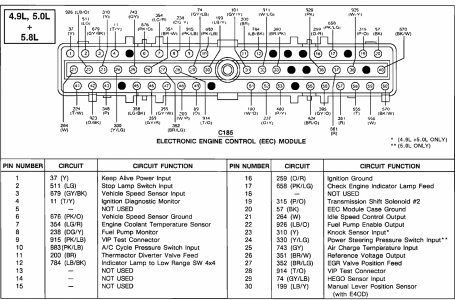
With that, below are your main PCM ground locations, their corresponding PCM terminal locations along with a simple volt-drop test that will expose a compromised ground RIGHT now.


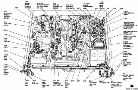
G101 at 8:00 is the main PCM ground, and G104 at 2:00 is the EEC module case ground

1662701833871.png


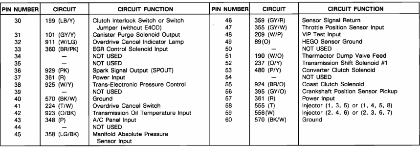
G101 grounds pins 60 and 40 at the PCM connector
G104 grounds the PCM case at pin 20

(Following tests are golden; accessing those terminals at PCM connector? Not so much. BUT... If you're going in after some PCM guts, you have to do all this anyway)

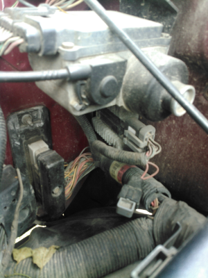
You'll need to disconnect PCM connector with 10mm socket down at the LH firewall, below and to the left of the brake booster. Cruise control might be in the way.

1662704505554.png


Then you'll need to release the tabs and remove that black plastic cover off the PCM connector for circuit access. Then remove the PCM. Two 11mm (7/16") nuts, one on each end top and bottom, and the plastic PCM retainer case slides out, followed by the PCM. From there, you can manipulate the connector so it is better angled and exposed for testing when you plug it back in with that 10mm fastener.
(And yes, this is why Ford had the original EEC IV Breakout Box built: so much easier)

With DVOM black lead in middle of battery negative post and red lead back-probing each ground pin 20, 40 and 60, KOEO (or KOER) (luckily, they are the fat black wires all lined up on the same end of the connector for easiest access)

You want to measure .050 volt drop or less at each pin. Key on or engine running is important.

Anything higher than .050 volt is a ground problem you'll have to track down.

If .050 or less, they're in very good shape, no more ground chasing needed, nothing to see here.

1662701908747.png
1662701955337.png

Good luck and happy hunting!
 
Last edited:
OP
OP
griff

griff

Member
Joined
Jun 25, 2010
Messages
45
Reaction score
22
Location
Chicagoland
Bad caps is a good call. I know you checked the grounds, but there are many. The main ground for the pcm and hegos is a blk/grn wire and should be near the battery. It grounds to the inner fender. If that one goes south, you can get all of your symptoms including inability to communicate with the pcm. (Very similar symptoms to bad caps)
If you don’t see anything when you look inside. Check that ground close. Sorry, I dont have my service info handy for a diagram and ground location.
Good luck
Cheers
Thanks Bronc!
 
OP
OP
griff

griff

Member
Joined
Jun 25, 2010
Messages
45
Reaction score
22
Location
Chicagoland
Agreed, and I do have my service data handy.


I'm not doubting or second-guessing you @griff
These grounds can sometimes have a lot of internal resistance that may not show up with a visual. But a loaded volt drop test will find them every time.

With that, below are your main PCM ground locations, their corresponding PCM terminal locations along with a simple volt-drop test that will expose a compromised ground RIGHT now.


G101 at 8:00 is the main PCM ground, and G104 at 2:00 is the EEC module case ground

View attachment 30401


G101 grounds pins 60 and 40 at the PCM connector
G104 grounds the PCM case at pin 20

(Following tests are golden; accessing those terminals at PCM connector? Not so much. BUT... If you're going in after some PCM guts, you have to do all this anyway)

You'll need to disconnect PCM connector with 10mm socket down at the LH firewall, below and to the left of the brake booster. Cruise control might be in the way.

View attachment 30404


Then you'll need to release the tabs and remove that black plastic cover off the PCM connector for circuit access. Then remove the PCM. Two 11mm (7/16") nuts, one on each end top and bottom, and the plastic PCM retainer case slides out, followed by the PCM. From there, you can manipulate the connector so it is better angled and exposed for testing when you plug it back in with that 10mm fastener.
(And yes, this is why Ford had the original EEC IV Breakout Box built: so much easier)

With DVOM black lead in middle of battery negative post and red lead back-probing each ground pin 20, 40 and 60, KOEO (or KOER) (luckily, they are the fat black wires all lined up on the same end of the connector for easiest access)

You want to measure .050 volt drop or less at each pin. Key on or engine running is important.

Anything higher than .050 volt is a ground problem you'll have to track down.

If .050 or less, they're in very good shape, no more ground chasing needed, nothing to see here.

View attachment 30402
View attachment 30403

Good luck and happy hunting!
This info and diagrams/photo are going to make troubleshooting smoother. You've provided a ton of help and I really appreciate the support Motech.
 

L\Bronco

Well-known member
Joined
Feb 28, 2022
Messages
800
Reaction score
852
Location
A.B. Canada
Agreed, and I do have my service data handy.


I'm not doubting or second-guessing you @griff
These grounds can sometimes have a lot of internal resistance that may not show up with a visual. But a loaded volt drop test will find them every time.

With that, below are your main PCM ground locations, their corresponding PCM terminal locations along with a simple volt-drop test that will expose a compromised ground RIGHT now.


G101 at 8:00 is the main PCM ground, and G104 at 2:00 is the EEC module case ground

View attachment 30401


G101 grounds pins 60 and 40 at the PCM connector
G104 grounds the PCM case at pin 20

(Following tests are golden; accessing those terminals at PCM connector? Not so much. BUT... If you're going in after some PCM guts, you have to do all this anyway)

You'll need to disconnect PCM connector with 10mm socket down at the LH firewall, below and to the left of the brake booster. Cruise control might be in the way.

View attachment 30404


Then you'll need to release the tabs and remove that black plastic cover off the PCM connector for circuit access. Then remove the PCM. Two 11mm (7/16") nuts, one on each end top and bottom, and the plastic PCM retainer case slides out, followed by the PCM. From there, you can manipulate the connector so it is better angled and exposed for testing when you plug it back in with that 10mm fastener.
(And yes, this is why Ford had the original EEC IV Breakout Box built: so much easier)

With DVOM black lead in middle of battery negative post and red lead back-probing each ground pin 20, 40 and 60, KOEO (or KOER) (luckily, they are the fat black wires all lined up on the same end of the connector for easiest access)

You want to measure .050 volt drop or less at each pin. Key on or engine running is important.

Anything higher than .050 volt is a ground problem you'll have to track down.

If .050 or less, they're in very good shape, no more ground chasing needed, nothing to see here.

View attachment 30402
View attachment 30403

Good luck and happy hunting!
Thanks Motech!
Awesome info! (Loaded voltage loss is the only way!)
Cheers
 
OP
OP
griff

griff

Member
Joined
Jun 25, 2010
Messages
45
Reaction score
22
Location
Chicagoland
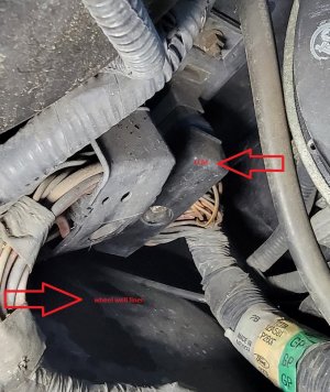
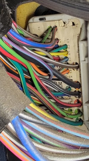
The inner wheel well liner blocks removal of ECM/PCM. Also, the other photo shows the ECM/PCM coming through the lower left cab firewall (left rear of break pedal)
 

Attachments

  • 20220909_144326.jpg
    20220909_144326.jpg
    232.6 KB · Views: 7
  • 20220909_144050.jpg
    20220909_144050.jpg
    133.1 KB · Views: 5

Motech

Well-known member
Joined
Jun 21, 2021
Messages
494
Reaction score
585
Location
Santa Cruz, CA:
The inner wheel well liner blocks removal of ECM/PCM.
Oops, forgot about that.

A pry bar flexing the plastic inner wheel well downward creates enough space to pull it right out.

Also, the other photo shows the ECM/PCM coming through the lower left cab firewall (left rear of break pedal)

I believe that's the inboard bulkhead connector. There are no PCM wires in there aside from the Check Engine light lead up behind the cluster.
 
OP
OP
griff

griff

Member
Joined
Jun 25, 2010
Messages
45
Reaction score
22
Location
Chicagoland
Oops, forgot about that.

A pry bar flexing the plastic inner wheel well downward creates enough space to pull it right out.


I believe that's the inboard bulkhead connector. There are no PCM wires in there aside from the Check Engine light lead up behind the cluster.
Thanks for that info Motech. I wasn't sure about what I was getting into there!. I got the wheel well bent so I am going to wrestle with those bolts under the hood now.
 
OP
OP
griff

griff

Member
Joined
Jun 25, 2010
Messages
45
Reaction score
22
Location
Chicagoland
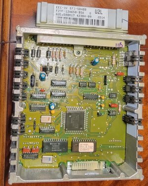
I got the EEC-IV out after wrestling with wire sets blocking it's exit. Your advice was spot on Motech regarding working from the wheel well. Once the unit is pulled, a star bit screwdriver is necessary to access the EEC-IV circuit board within.

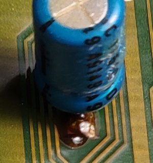
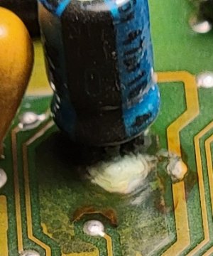
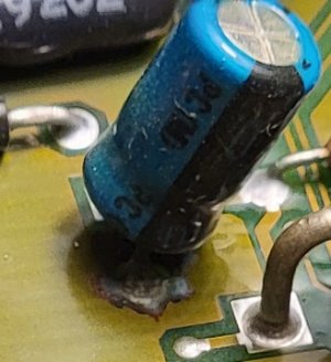
These photos show the corrosion/leakage from the three capacitors, as well as the entire inner unit. No obvious blown capacitor tops, all are flat. I'll replace them for $14 and return the unit.
 

Attachments

  • 20220909_171953.jpg
    20220909_171953.jpg
    60.5 KB · Views: 4
  • 20220909_172117.jpg
    20220909_172117.jpg
    69 KB · Views: 4
  • 20220909_172221.jpg
    20220909_172221.jpg
    58.4 KB · Views: 4
  • 20220909_172344.jpg
    20220909_172344.jpg
    344.4 KB · Views: 5
OP
OP
griff

griff

Member
Joined
Jun 25, 2010
Messages
45
Reaction score
22
Location
Chicagoland
Will report back ASAP. Getting the capacitors is an entirely different story. Two are 47uf/16v 105c, one 10uf/63v 105c. Ofc I've found one but not the other!
 

chrlsful

Active member
Joined
Oct 13, 2009
Messages
432
Reaction score
218
Location
S. Amherst, MA 01002-1827
subscribed'n "all eyes". Gota

'93 Ranger in the shop's actin funny.
Cant read the OBD I codes (13? 33?) and
may doa visual inspection below that same
bulkhead 'clip'. "envy of a skillet" brought me
to this thread - but as these things age and prts
become unavailable we all might need to stretch to
take care of neighbors (THIS garage's main) or keep
our own runnin... thnx to all who contribute here~
 

Members online

No members online now.

Forum statistics

Threads
22,621
Messages
136,701
Members
25,282
Latest member
79' Buckin Bronco
Top