Inaccurate Ambient Air Temp Readings, ‘96 E.B Overhead Display

Disclaimer: Links on this page pointing to Amazon, eBay and other sites may include affiliate code. If you click them and make a purchase, we may earn a small commission.

BentSpurs

Member
Joined
May 13, 2021
Messages
31
Reaction score
36
Location
Peachtree Corners, GA
After replacing a leaky capacitor in the controller board for the digital display in the overhead console of our ‘96 Bronco Eddie Bauer, it’s once again displaying the compass and air temp. Recently though the air temp reading is fluctuating from actual. Any ideas on a fix? Thanks in advance!
 

Tiha

Well-known member
Staff member
Moderator
Joined
Jul 22, 2020
Messages
1,085
Reaction score
1,109
Location
Midwest
I am actually fighting the same problem. I would imagine try and replace the outside temp sensor first.

After that have to dig into voltages and looking for bad wires.

Mine seems to be reading 10 degrees or so hotter most of the time.
 

L\Bronco

Well-known member
Joined
Feb 28, 2022
Messages
800
Reaction score
851
Location
A.B. Canada
I am actually fighting the same problem. I would imagine try and replace the outside temp sensor first.

After that have to dig into voltages and looking for bad wires.

Mine seems to be reading 10 degrees or so hotter most of the time.
Just looked through the Ford service info diagnostics for temp accuracy. It simply says verify wiring continuity between the overhead compass and the sensor, then replace the sensor.
Sorry, not much help there.
Cheers
 

Tiha

Well-known member
Staff member
Moderator
Joined
Jul 22, 2020
Messages
1,085
Reaction score
1,109
Location
Midwest
The wires are labeled sensor + and sensor - if I remember correctly.

So not sure what the voltage should be, but maybe one of these days I will actually test it and post up.

Maybe measure the resistance of the sensor as well as recording the temp at the time measured.
 
OP
OP
BentSpurs

BentSpurs

Member
Joined
May 13, 2021
Messages
31
Reaction score
36
Location
Peachtree Corners, GA
I am actually fighting the same problem. I would imagine try and replace the outside temp sensor first.

After that have to dig into voltages and looking for bad wires.

Mine seems to be reading 10 degrees or so hotter most of the time.
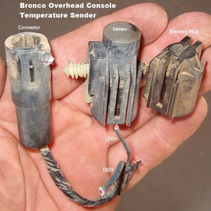
Did find this which is helpful over at SuperMotors, thanks Steve! https://www.supermotors.net/registry/media/651946
 

Motech

Well-known member
Joined
Jun 21, 2021
Messages
494
Reaction score
585
Location
Santa Cruz, CA:
Did find this which is helpful over at SuperMotors, thanks Steve! https://www.supermotors.net/registry/media/651946
Pic from your link:

1668142436733.png

What I often find--and it's universal, not jusat Ford--is the sensor no longer lives in the cocoon where it originally was mounted. For instance, that style there might become dislodged from the white push-pin bracket and is dangling or shoved up somewhere more exposed to wind and elements. This will cause erratic readings, more dramatic when in motion, and reestablishing it's protected location will fix it.

Mine seems to be reading 10 degrees or so hotter most of the time.

If yours is consistently 10* hotter under all driving conditions, you may have some circuit resistance on the signal side. A simple test would be a jumper wire from sensor feedback source back-probed into sensor positive. If it corrects, sanitize your redundant bypass circuit and make it permanent.

If it does not correct, adding a little resistance to the ground side will bring temp values down.
 

Tiha

Well-known member
Staff member
Moderator
Joined
Jul 22, 2020
Messages
1,085
Reaction score
1,109
Location
Midwest
If yours is consistently 10* hotter under all driving conditions, you may have some circuit resistance on the signal side. A simple test would be a jumper wire from sensor feedback source back-probed into sensor positive. If it corrects, sanitize your redundant bypass circuit and make it permanent.

If it does not correct, adding a little resistance to the ground side will bring temp values down.
That is helpful, Thank you.

Another thing I keep thinking about is Vehicle speed sensor. The overhead console looks at vehicle speed.

I have a gear vendor, When I removed the GV electronics I clipped the wire to the VSS, I am wondering it I inadvertently disconnected the temp display from it as well.

Funny how sitting around like this, such a little project but never a priority. LOL
 

Motech

Well-known member
Joined
Jun 21, 2021
Messages
494
Reaction score
585
Location
Santa Cruz, CA:
That is helpful, Thank you.

You're welcome.

The wires are labeled sensor + and sensor - if I remember correctly.

So not sure what the voltage should be, but maybe one of these days I will actually test it and post up.

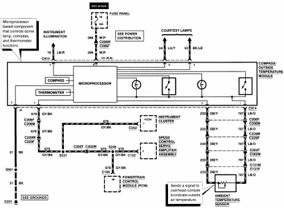
It is likely a 5v reference, and appears to be created by the microprocessor within the overhead module itself. Same with the ground, taken off the main interior body ground G201, then buffered for a more isolated sensor ground within that same microprocessor.

Notice the ambient temp sensor circuits flow through five individual connectors before the signal reaches the processor? It's born to fail at some level or another!

Here's your factory diagram:

1668233510641.png

When you get a bug to check it out, locate and measure volt drop on circuit 233 between C131 and C914. it only takes a very small volt drop--like 50-100 mV--to noticeably skew your accuracy upwards. You might as well do the same test on circuit 767 while you're there, but volt drop there would trend your temp reading downward.

Another thing I keep thinking about is Vehicle speed sensor. The overhead console looks at vehicle speed.

I have a gear vendor, When I removed the GV electronics I clipped the wire to the VSS, I am wondering it I inadvertently disconnected the temp display from it as well.

Don't think you have any worries there. As you can see, even though the temp sensor and VSS circuits share four common connectors, they are all completely isolated from VSS sensor itself. Temp sensor gets both feeds directly from processor while the VSS signal comes from the PCM, the VSS authority. It is fed the analog signal directly from the sensor, and that's the only component the VSS is connected to. The PCM takes and converts that analog signal t a proper digital signal the other modules can process and hands it out to them.

If your GV system tapped into the analog VSS feed directly, as the PCM does, then it too must be internally converting to digital.

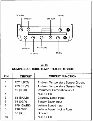
Here's your connector view:

1668233274281.png
 

miesk5

96 Bronco 5.0
Staff member
Moderator
Joined
Oct 18, 2005
Messages
9,078
Reaction score
1,035
Location
Floating in the Pacific
Yo,
FYI, IF NEEDED;
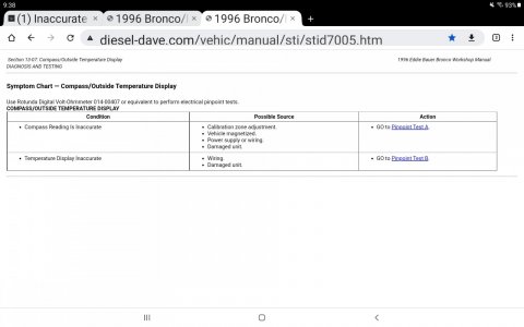
"
Section 13-07: Compass/Outside Temperature Display
1996 Eddie Bauer Bronco Workshop Manual​
DESCRIPTION AND OPERATION

Factors Affecting Accuracy​

Various internal and external conditions can affect compass accuracy.

  • Magnetic mount devices (antennas, racks, etc.) should not be located near the magnetic sensor. Use of these devices near the sensor will cause the compass to be inaccurate. If these devices must be used, the compass should be recalibrated using the zone and calibration adjustments.
  • Driving near power lines or objects with high iron or steel content (bridges, underground pipes and tunnels, etc.) may temporarily change the compass heading. The display will return to the true vehicle heading after the vehicle leaves the area.
  • In most locations, magnetic north differs from the "true north" direction shown on maps (geographic north). This difference changes considerably across the country anywhere from 25 degrees to the east to 30 degrees to the west. This misalignment can be corrected on the compass by performing the Zone Adjustment procedure described in the Adjustments portion of this section.
The temperature display operates through the use of a thermometer sensor (15A022) mounted behind the front bumper/grille. The display can be changed from English to metric units.

To update the temperature, the module processes data from the sensor to make sure engine heat does not affect the displayed temperature. Upon starting the vehicle, the module checks the temperature and how long the ignition switch has been off. These parameters are described by one of three groups below.

Engine Cold

If ignition has been on for less than five minutes, and was previously off for longer than two hours, the engine is cold and does not affect the temperature sensor. Current sensor data is used.

Engine Warm, Updated Temperature Cooler

If ignition has been on for longer than five minutes or if the ignition was off for less than two hours, the engine compartment may be warm from the heat of the engine. The current temperature is displayed only if it is less than the stored temperature reading.

Engine Warm, Updated Temperature Warmer

If the sensor data indicates a higher temperature, the module uses a high-speed counter to monitor vehicle speed to determine whether engine heat is causing erroneous readings. The counter is incremented when the speed is greater than 53 km/h (33 mph) and decremented when the speed is between 16 and 53 km/h (10-33 mph). If the speed is less than 16 km/h (10 mph), the counter is reset, and the displayed temperature is not updated from its last reading. If the counter is greater than two minutes, the currently sensed temperature is displayed. If the high-speed counter has counted less than two minutes, the temperature can increase only one degree per minute.

If the temperature sensor is short- or open-circuited, the display will read SC or OC, respectively. If the temperature drops below 3°C (38°F), or is below 3°C (38°F) upon power-up, the display will alternate between displaying ICE and the temperature. The display will alternate every two seconds for a time of one minute."

Screenshot_20221112-093842_Chrome.jpg


Section 13-07: Compass/Outside Temperature Display
1996 Eddie Bauer Bronco Workshop Manual​
DESCRIPTION AND OPERATION

Factors Affecting Accuracy​

Various internal and external conditions can affect compass accuracy.

  • Magnetic mount devices (antennas, racks, etc.) should not be located near the magnetic sensor. Use of these devices near the sensor will cause the compass to be inaccurate. If these devices must be used, the compass should be recalibrated using the zone and calibration adjustments.
  • Driving near power lines or objects with high iron or steel content (bridges, underground pipes and tunnels, etc.) may temporarily change the compass heading. The display will return to the true vehicle heading after the vehicle leaves the area.
  • In most locations, magnetic north differs from the "true north" direction shown on maps (geographic north). This difference changes considerably across the country anywhere from 25 degrees to the east to 30 degrees to the west. This misalignment can be corrected on the compass by performing the Zone Adjustment procedure described in the Adjustments portion of this section.
The temperature display operates through the use of a thermometer sensor (15A022) mounted behind the front bumper/grille. The display can be changed from English to metric units.

To update the temperature, the module processes data from the sensor to make sure engine heat does not affect the displayed temperature. Upon starting the vehicle, the module checks the temperature and how long the ignition switch has been off. These parameters are described by one of three groups below.

Engine Cold

If ignition has been on for less than five minutes, and was previously off for longer than two hours, the engine is cold and does not affect the temperature sensor. Current sensor data is used.

Engine Warm, Updated Temperature Cooler

If ignition has been on for longer than five minutes or if the ignition was off for less than two hours, the engine compartment may be warm from the heat of the engine. The current temperature is displayed only if it is less than the stored temperature reading.

Engine Warm, Updated Temperature Warmer

If the sensor data indicates a higher temperature, the module uses a high-speed counter to monitor vehicle speed to determine whether engine heat is causing erroneous readings. The counter is incremented when the speed is greater than 53 km/h (33 mph) and decremented when the speed is between 16 and 53 km/h (10-33 mph). If the speed is less than 16 km/h (10 mph), the counter is reset, and the displayed temperature is not updated from its last reading. If the counter is greater than two minutes, the currently sensed temperature is displayed. If the high-speed counter has counted less than two minutes, the temperature can increase only one degree per minute.

If the temperature sensor is short- or open-circuited, the display will read SC or OC, respectively. If the temperature drops below 3°C (38°F), or is below 3°C (38°F) upon power-up, the display will alternate between displaying ICE and the temperature. The display will alternate every two seconds for a time of one minute.

PINPOINT TEST B: TEMPERATURE DISPLAY INACCURATE​


B1 SENSOR CIRCUIT TEST​

  • Disconnect overhead console 10-pin connector and temperature sensor 2-pin connector.
  • Using Rotunda Digital Volt-Ohmmeter 014-00407 or equivalent, verify continuity between 10-pin connector Pin 2, Circuit 233 (DB/Y) and 2-pin connector Circuit 233 (DB/Y).
Is continuity present?
YesNo
GO to B2.SERVICE Circuit 233 (DB/Y) for open. RETEST system.

B2 CONTINUITY CHECK​

  • Using Rotunda Digital Volt-Ohmmeter 014-00407 or equivalent, verify continuity between 2-pin connector Circuit 767 (LB/O) at ambient sensor and compass/outside temperature module connector Pin 1.
Is continuity present?
YesNo
REPLACE thermometer sensor. RETEST system.SERVICE Circuit 767 (LB/O) for open. RETEST system.


wyo58

Member
Joined
Jan 9, 2022
Messages
77
Reaction score
63
Location
Laramie WY
The wires are labeled sensor + and sensor - if I remember correctly.

So not sure what the voltage should be, but maybe one of these days I will actually test it and post up.

Maybe measure the resistance of the sensor as well as recording the temp at the time measured.
I kind of remember the + and - maybe because they were shielded cable?
 

Motech

Well-known member
Joined
Jun 21, 2021
Messages
494
Reaction score
585
Location
Santa Cruz, CA:
I kind of remember the + and - maybe because they were shielded cable?

Nah, it's not that advanced. It's a simple thermistor style sensor, like coolant or intake air sensors. Since it hangs out in the atmosphere instead of threaded into steel like the others, it needs it's own dedicated ground circuit.
 

Similar threads

T
Replies
0
Views
1K
Top stories on BroncoZone.com
T
T
Replies
0
Views
2K
Top stories on BroncoZone.com
T
T
Replies
0
Views
1K
Top stories on BroncoZone.com
T
T
Replies
0
Views
1K
Top stories on BroncoZone.com
T

Members online

No members online now.

Forum statistics

Threads
22,621
Messages
136,700
Members
25,282
Latest member
79' Buckin Bronco
Top