Crazy Electrical

Disclaimer: Links on this page pointing to Amazon, eBay and other sites may include affiliate code. If you click them and make a purchase, we may earn a small commission.

ajrose79

New member
Joined
Sep 10, 2021
Messages
13
Reaction score
11
Location
Buxton, NC
Hey guys, I decided to take a break from getting the tailgate window working, but I have noticed some crazy things today when I drove my daughter’s 1992 Bronco XLT 351, the RPM needle will not drop below 2500; the headlight switch is off, but the park lights are on, the red brake light and Rear ABS lights are on, fluid level is okay, and last the fuel gauge doesn’t work. I am beginning to think there’s a bad ground wire or something going. Any advice on where to start looking would be greatly appreciated.
 

miesk5

96 Bronco 5.0
Staff member
Moderator
Joined
Oct 18, 2005
Messages
9,078
Reaction score
1,035
Location
Floating in the Pacific
Yo AJ,
GROUND G201 IS IN DRIVER KICK PANEL
Start with HEADLIGHT Switch Fires, Part Number SW-2103: "...Over the past two years, this office has experienced fires caused by another potential problem in Ford vehicles. The problem exists within the dimmer portion of the headlight switch in Ford vehicles. The light switch involved is a Model SW-2103. These are the pull out type headlight switches usually located in the lower left corner of the front dash of Ford vehicles. The headlight portion of the switch has two pullout positions, the first for parking lights only, and fully out for headlights and parking lights. The shaft of this pull-out light switch can be turned clockwise and counterclockwise which activates a dimmer switch, lowering and raising the intensity of the lighting in the instrument panels respectively. Fully rotating the shaft counterclockwise past a notch activates the interior lights within the vehicles. The potential problem exists within the dimmer portion of this switch. The dimmer mechanism consists of a metallic resistive coil set inside a ceramic disc positioned over the shaft of the switch. The coil is exposed on its front side away from the passenger compartment. The front side of the coil passes across a contact permitting a current to flow through a certain portion of the coil when the switch is pulled our in its first or second positions. The greater amount of coil through which the current is permitted to pass (clockwise most position) creates the greatest resistance and therefore dims the dash lighting to its lowest intensity. The opposite position provides greatest intensity. Through our investigations, we have found that the coil can fail owing to wear and/or possible material defects or damage. A fractured coil can maneuver itself free of the ceramic disc permitting it to come in contact with the metal bracket which mounts and grounds the switch to the vehicle. When this occurs, a current can flow through a portion of the coil creating high temperatures melting the metal material of the coil and possibly igniting surrounding combustibles. This mechanism has been observed in three separate incidents by this office. Two of these resulted in a fire. The mechanism is precipitated by wear and/or defect in the coil mechanism. If the former is true, we expect there will be an increase in fires caused through this mechanism given an increase in service time. To this date the problem appears to be somewhat limited. However, this particular light switch has been utilized in numerous Ford vehicles. Therefore, a small increase in failure rate owing to age and wear could result in a significant increase in fire losses. The SW-2103 Light Switch Assembly discussed above is reportedly installed in the following Ford vehicles: 1986 -1997 F100, F150, F300; 1990-1994 Explorer; 1987-1994 Ranger; 1987-1990 Bronco II; 1992-1997 Aerostar..."

miesk5 NOTE: No Bronco Listed, but this may be the result of typos or incomplete research by the company.
And some Full-Size Bronco owners have had these fires.

Tailgate:
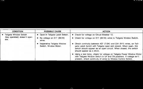
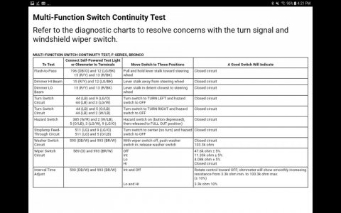
Screenshot_20210913-074023_Gallery.jpg

Screenshot_20210913-073035_Gallery.jpg

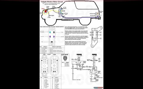
All '80-96 t/g wiring runs from the dash switch (F2TZ-14529-A Motorcraft SW7071 ~$25~65) out the firewall along the frame to the rear bumper up to the L taillight and into the t/g. '80-86 have a large round 3-wire connector in the LHR taillight well; those with rear defrost also have a 1-wire connector. All years with rear defrost have a ground ring ******* to the body in the taillight well. I think '87-91 have the large round connector in front of the taillight AND a smaller round 4-wire connector inside the frame at the LHR body mount. '92-96 only have the frame connector.

Normal operation is as follows:

RAISE from the dash switch:
Power flows thru fuse 14 thru the LB/BK wire thru the IP switch UP contacts thru the P/LG wire thru the key switch UP contacts thru the Y/R wire to the motor brushes, commutator, & windings; then it grounds thru the motor's internal CB, out thru the R/Y wire thru the latch switch thru the T/Bk wire thru the key switch DOWN contacts thru the Pk/LB wire thru the IP switch DOWN contacts to the Bk wire to the ground in the kick panel (or dash on older Broncos).

LOWER from the dash switch:
Power flows thru fuse 14 thru the LB/BK wire thru the IP switch DOWN contacts thru the Pk/LB wire thru the key switch DOWN contacts thru the T/Bk wire thru the latch switch thru the R/Y wire thru the motor's internal CB to the motor brushes, commutator, & windings; then it grounds out thru the Y/R wire thru the key switch UP contacts thru the P/LG wire thru the IP switch UP contacts to the Bk wire to the ground in the kick panel (or dash on older Broncos).

RAISE from the key switch:
Power flows thru fuse 12 thru the BK/Wh wire thru the key switch thru the UP contacts thru the Y/R wire to the motor brushes, commutator, & windings; then it grounds thru the motor's internal CB out thru the R/Y wire thru the latch switch thru the T/Bk wire thru the key switch DOWN contacts thru the Pk/LB wire thru the IP switch DOWN contacts to the Bk wire to the ground in the kick panel (or dash on older Broncos).

LOWER from the key switch:
Power flows thru fuse 12 thru the BK/Wh wire thru the key switch DOWN contacts thru the T/Bk wire thru the latch switch thru the R/Y wire thru the motor's internal CB to the motor brushes, commutator, & windings; then it grounds out thru the Y/R wire thru the key switch UP contacts thru the P/LG wire thru the IP switch UP contacts to the Bk wire to the ground in the kick panel (or dash on older Broncos).

Note that in ALL cases, EVERY switch is used, and the circuit ALWAYS grounds at the same point.

TACHOMETER:
 
Last edited:

miesk5

96 Bronco 5.0
Staff member
Moderator
Joined
Oct 18, 2005
Messages
9,078
Reaction score
1,035
Location
Floating in the Pacific
Yo,
This site has too many character limitations!
Tach:
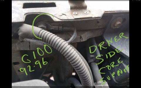
GROUNDS ARE G201 AGAIN & G100
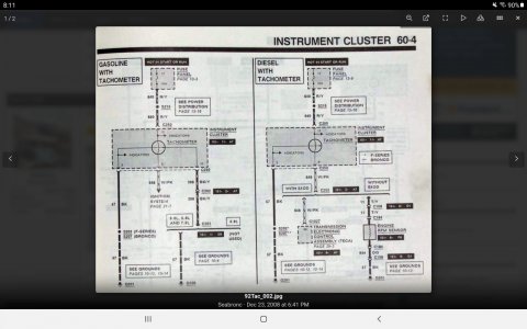
Screenshot_20210913-081116_Chrome.jpg


Screenshot_20210913-074211_Gallery.jpg

The Tachometer is an electrically operated gauge that indicates engine speed in rpm. In vehicles with gasoline engines. the Tachometer receives its voltage pulses from the ignition coil when the engine is running.
TACHOMETER INOPERATIVE, ERRATIC, WRONG INDICATION, GASOLINE ENGINE
L1 CHECK FUSE

  • Check fuse.
Is fuse blown?
YesNo
REPLACE fuse. If fuse blows again, CHECK for short in circuit.GO to L2.
L2 CHECK WIRING
  • Check for loose wiring connections in engine compartment or at instrument cluster.
  • miesk5 Note, tach connector at coil is subject to corrosion, damage, looseness, etc
Are connections loose?
YesNo
SECURE loose connections.GO to L3.
L3 CHECK INSTRUMENT CLUSTER PRINTED CIRCUIT
  • Inspect instrument cluster printed circuit for damage, poor connections, or open circuits. miesk5 Note, - The 20-ohm resistor is located on the instrument cluster backplate flexible circuit. it could be a loose connection to PCB, etc
Is instrument cluster printed circuit open or damaged?
YesNo
REPLACE or REPAIR instrument cluster.GO to L4.
L4 MAKE RESISTANCE/VOLTAGE CHECKS
  • ani_caut.gif CAUTION: Before checking the continuity of any circuit, make sure there is no voltage present in the circuit prior to switching the test equipment to the resistance function to avoid damage to equipment. Refer to the equipment user's manual for additional information.
  • Remove instrument cluster and make resistance and voltage checks (using Rotunda 88 Digital Multimeter 105-00053 or equivalent) at 14401 wiring harness connector as follows:
    • Check Pin No. 3 (Connector 1) resistance to chassis ground should read 1 ohm or less.
    • Check Pin No. 10 (Connector 1) resistance to chassis ground � should read 1 ohm or less, if vehicle has 8-cylinder engine. Open circuit if 6-cylinder engine.
    • Check Pin No. 9 (Connector 1) resistance to negative terminal of ignition coil should be 1 ohm or less.
    • ani_caut.gif CAUTION: Make sure multimeter is in the voltage function and not in the resistance function to avoid damage to multimeter.
    • Connect battery. Key to RUN. Check for +12 volts at Pin No. 13 (Connector 1). Turn ignition OFF. Disconnect battery.

YesNo
Condition is not in tachometer. SERVICE wiring.REPLACE tachometer.


View attachment 173632
Cluster Printed Circuit in 92-96; "...The instrument cluster printed circuit (10K843) which supplies current to the instrument panel indicators, gauges, and some clocks, is made of copper foil which is bonded to a polyester base film (usually referred to as Mylar®). The instrument cluster printed circuit is mounted to the cluster housing and, due to its location, cannot be easily inspected or tested in the vehicle. This makes the instrument cluster printed circuit vulnerable to damage when a probe is used for in-vehicle testing as the probe can pierce the instrument cluster printed circuit or, in some cases, burn the copper conductor.
Since there is no approved procedure for in-vehicle testing of the instrument cluster printed circuit, it must be removed for visual inspection. If no visual damage is evident, each circuit should be tested with an ohmmeter. If an open circuit or short is detected, the instrument cluster printed circuit must be replaced..." by Ford via Steve
View attachment 173633View attachment 173634

 
Last edited:

miesk5

96 Bronco 5.0
Staff member
Moderator
Joined
Oct 18, 2005
Messages
9,078
Reaction score
1,035
Location
Floating in the Pacific
Yo
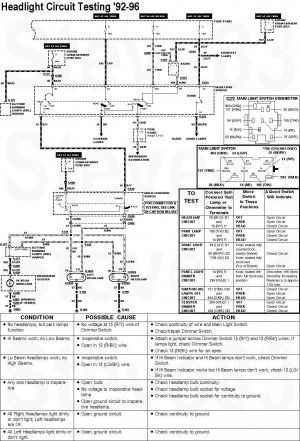
PARK LIGHTS:
GROUND G100 AGAIN! & G101
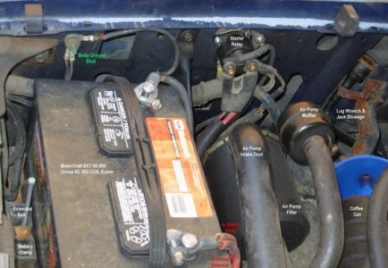
G101 location pic in 92-96; marked as "Body Ground Stud" by BANNED MEMBER
enginebay93rhf.jpg


GROUNDS G100, G101 & G201 AGAIN!
headlights92.jpg

Screenshot_20210913-074055_Gallery.jpg
 

Attachments

  • ani_caut.gif
    ani_caut.gif
    854 bytes · Views: 5
  • ani_caut.gif
    ani_caut.gif
    854 bytes · Views: 6
Last edited:

miesk5

96 Bronco 5.0
Staff member
Moderator
Joined
Oct 18, 2005
Messages
9,078
Reaction score
1,035
Location
Floating in the Pacific
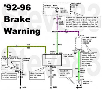
Red ABS WARNING LIGHT;
GROUNDS G100 & G201 AGAIN!
brakewarn92.jpg
The red warning light for the brakes can show three things -- that either the parking brake is not fully released, that the brake fluid level is low in the master cylinder reservoir or the vacuum pressure is low on diesel engine vehicles.
 
Joined
Sep 18, 2019
Messages
41
Reaction score
43
Location
luttrell, tn
Hey guys, I decided to take a break from getting the tailgate window working, but I have noticed some crazy things today when I drove my daughter’s 1992 Bronco XLT 351, the RPM needle will not drop below 2500; the headlight switch is off, but the park lights are on, the red brake light and Rear ABS lights are on, fluid level is okay, and last the fuel gauge doesn’t work. I am beginning to think there’s a bad ground wire or something going. Any advice on where to start looking would be greatly appreciated.
i kinda had some of the same weird like symptoms on my 93 bro, i would fire her up, pull the headlites and it would die, hit the brakes the headlites would come on, blinkers would show on but wouldnt blink... weird stuff, i cleaned and wd'ed what grounds i could find then went online and bought 3-4 ground cables and ran them from batt to body, frame to body, frame to motor... problem solved for cheap... mine sits outside so it draws moisture
 
OP
OP
A

ajrose79

New member
Joined
Sep 10, 2021
Messages
13
Reaction score
11
Location
Buxton, NC
Yo,
FUEL GAUGE:
WELCOME G1OO TO THE PARTY!
You have been a great help! I am wondering if when you radiator busted if it caused all these problems since one the grounds in on side where the radiator busted in the near battery.
 
OP
OP
A

ajrose79

New member
Joined
Sep 10, 2021
Messages
13
Reaction score
11
Location
Buxton, NC
i kinda had some of the same weird like symptoms on my 93 bro, i would fire her up, pull the headlites and it would die, hit the brakes the headlites would come on, blinkers would show on but wouldnt blink... weird stuff, i cleaned and wd'ed what grounds i could find then went online and bought 3-4 ground cables and ran them from batt to body, frame to body, frame to motor... problem solved for cheap... mine sits outside so it draws moisture
An you share where you purchased the cables and exactly where you grounded them at.
 

miesk5

96 Bronco 5.0
Staff member
Moderator
Joined
Oct 18, 2005
Messages
9,078
Reaction score
1,035
Location
Floating in the Pacific
You have been a great help! I am wondering if when you radiator busted if it caused all these problems since one the grounds in on side where the radiator busted in the near battery.
Yo AJ,
LEAK may have caused issues.
Major Grounds:
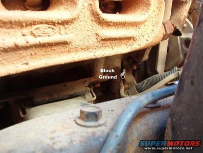
wm64enggnd.jpg
Engine Block pic in a 94 5.8; "...The black battery wire goes from the front bolt of the engine mount (on the block) to this tab & up to the battery post, where a smaller black wire goes to the core support, providing a continuous ground path between the engine, frame, battery, & body..."
Source: by CodysBigBlueBronco (how much $???) at


Frame in a 94 5.8;
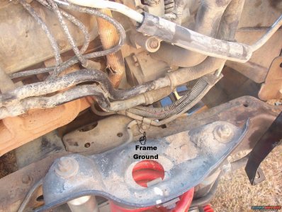
63framegnd.jpg
"...Frame ground just inboard of the R spring tower. The black battery wire goes from the front bolt of the engine mount (on the block) to this tab & up to the battery post, where a smaller black wire goes to the core support, providing a continuous ground path between the engine, frame, battery, & body..."
Source: by CodysBigBlueBronco (how much $???)

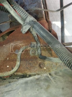
Frame Ground location (Passenger side Cross member above
engine mount)
20140508_165800.jpg
by jowens1126

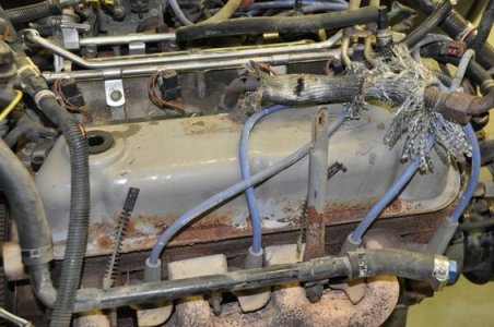
Intake Manifold to Block ******** oassenger side Location pic in a 96 5. by bossind
dsc_0015.jpg


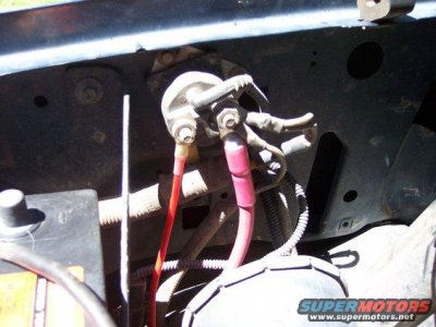
For future issues such as no crank, inspect STARTER RELAY GROUND; relay located on PASSENGER FENDER LINER, near battery, see this
Starter Relay pic in a 95
florence-wheeling-04042008-015.jpg
Source: by Shane C. (BigBlue, bigbluebronk)
Check for continuity between relay mounting bracket and inner fender. Rust, grime, paint etc interferes with relay control circuit.
 
Last edited:
OP
OP
A

ajrose79

New member
Joined
Sep 10, 2021
Messages
13
Reaction score
11
Location
Buxton, NC
Yo AJ,
LEAK may have caused issues.
Major Grounds:
View attachment 28525
Engine Block pic in a 94 5.8; "...The black battery wire goes from the front bolt of the engine mount (on the block) to this tab & up to the battery post, where a smaller black wire goes to the core support, providing a continuous ground path between the engine, frame, battery, & body..."
Source: by CodysBigBlueBronco (how much $???) at


Frame in a 94 5.8;
View attachment 28521
"...Frame ground just inboard of the R spring tower. The black battery wire goes from the front bolt of the engine mount (on the block) to this tab & up to the battery post, where a smaller black wire goes to the core support, providing a continuous ground path between the engine, frame, battery, & body..."
Source: by CodysBigBlueBronco (how much $???)

Frame Ground location (Passenger side Cross member above
engine mount)
View attachment 28522
by jowens1126

Intake Manifold to Block ******** oassenger side Location pic in a 96 5. by bossind
View attachment 28523


For future issues such as no crank, inspect STARTER RELAY GROUND; relay located on PASSENGER FENDER LINER, near battery, see this
Starter Relay pic in a 95
View attachment 28524
Source: by Shane C. (BigBlue, bigbluebronk)
Check for continuity between relay mounting bracket and inner fender. Rust, grime, paint etc interferes with relay control circuit.
Can i ask a silly question, Can the motor/engine be pressure washed? Can I open the hood cover the distributor cap well and pressure washer down the motor?
 

johnnyreb

Well-known member
Joined
Feb 23, 2021
Messages
2,511
Reaction score
1,096
Location
West Virginia
Can i ask a silly question, Can the motor/engine be pressure washed? Can I open the hood cover the distributor cap well and pressure washer down the motor?
On the older vehicles you could. On the late model and newer ones. They have alot of relays and things--its up to you. These electronic are so sensitive. It could cause alot of problems.Water could shorter them out and cause alot of problems. If it was mine--no I wouldn,t. I also don,t have a new one and the electronics is why I don,t want one.
 
OP
OP
A

ajrose79

New member
Joined
Sep 10, 2021
Messages
13
Reaction score
11
Location
Buxton, NC
On the older vehicles you could. On the late model and newer ones. They have alot of relays and things--its up to you. These electronic are so sensitive. It could cause alot of problems.Water could shorter them out and cause alot of problems. If it was mine--no I wouldn,t. I also don,t have a new one and the electronics is why I don,t want one.
It’s a 1992. At some point there was an oil leak, I just would like to clean it off.
 

johnnyreb

Well-known member
Joined
Feb 23, 2021
Messages
2,511
Reaction score
1,096
Location
West Virginia
It’s a 1992. At some point there was an oil leak, I just would like to clean it off.
Well Miensk will be on and he,ll tell you more about that year.Sorry. I think I,d first try wiping it off with dry rags . If your talk about the bottom of the motor and sides. I,d look it over good for wires and vaccum lines. Those high pressure washers are pretty powerful and could cause some troubles.
 
OP
OP
A

ajrose79

New member
Joined
Sep 10, 2021
Messages
13
Reaction score
11
Location
Buxton, NC
Well Miensk will be on and he,ll tell you more about that year.Sorry. I think I,d first try wiping it off with dry rags . If your talk about the bottom of the motor and sides. I,d look it over good for wires and vaccum lines. Those high pressure washers are pretty powerful and could cause some troubles.
Thank you!
 

johnnyreb

Well-known member
Joined
Feb 23, 2021
Messages
2,511
Reaction score
1,096
Location
West Virginia
Dorman 60213 15 In. Universal Ground Strap got them off amazon... if iremember i bought 3... i will take pix on where i attached them...
Seeing how its got a alumnium bell houseing. I,d put one on the starter side to the frame or motor if the cable is not long enough . Then one from the motor to the frame. ,make sure the areas are cleaned and any paint removed . Then I,d cover it with a little grease. To help keep moisture off them. I have to do the same today and I,ll try and get some picture this evening.
 

johnnyreb

Well-known member
Joined
Feb 23, 2021
Messages
2,511
Reaction score
1,096
Location
West Virginia
thank you!
Gotta admit they are high for no more what you get. I got regular ground--the size of battery cables--the big ones. Not the skinny ones. These little ones have a tendency to break during motion and body giving.
 

Members online

Forum statistics

Threads
22,621
Messages
136,701
Members
25,282
Latest member
79' Buckin Bronco
Top