yo J,
re: "....my fuel pressure reg went out and had my truck spewing black liquid out the tail pipe..." That will **** the Cat.
Here are some CC test Links; but you or that shop could remove the cat(s) & muffler/tp ezily and try running it.
Mine is bolted on and some PB Blaster and if necessary heat (MAP gas) along with a small wire brush or a Dremel w/wire wheel to clean up the bolt threads got the bolt out quickly.
Vacuum Test by walkerexhaust.com
another Test obviously reiterating Walker's
=========
AND da Mack Daddy of all CC Testing for Broncos and Ford truck/vans:
TSB 91-12-11 Catalytic Converter Diagnosis
Publication Date: JUNE 12, 1991
LIGHT TRUCK: 1986-91 BRONCO, ECONOLINE, F-150-350 SERIES
1988-91 F SUPER DUTY, F47
ISSUE: Lack of power or a no start condition may be diagnosed as an exhaust restriction caused by a plugged catalytic converter. A plugged catalytic converter (internal deterioration) is usually caused by abnormal engine operation.
ACTION: Diagnose the catalytic converter to confirm internal failure. Refer to the Catalyst and Exhaust System Diagnostic Section, in the Engine/Emissions Diagnostic Shop Manual and the following procedures for service details.
SERVICE PROCEDURE
1. Lack of proper HEGO operation may cause, or be the result of a rich or lean fuel condition, which could cause additional heat in the catalyst. Perform self test KOEO and KOER, service any codes.
NOTE: IF TWO DIGIT CODES 41, 42, 85 OR THREE DIGIT CODES 171, 172, 173, 179, 181, 182, 183 AND 565 ARE RECIEVED, CHECK FOR PROPER HEGO GROUND.
If the HEGO ground is good, the following areas may be at fault:
* Ignition Coil
* Distributor Cap
* Distributor Rotor
* Fouled Spark Plug
* Spark Plug Wires
* Air Filter
* Stuck Open Injector
* Fuel Contamination Engine OIL
* Manifold Leaks Intake/Exhaust
* Fuel Pressure
* Poor Power Ground
* Engine Not At Normal Operating Temperature
* HEGO Sensor
2. Spark timing that is ******** from specification may increase exhaust gas temperature and shorten catalyst life. Refer to the following procedure for service details.
a. Check spark timing. Check base timing with spout disconnected. Set base timing to the specification on the vehicle emission decal.
b. Check computed timing with spout connected.
NOTE: COMPUTED TIMING IS EQUAL TO BASE TIMING PLUS 20° BTDC ± 3°.
3. Misfiring spark plugs may cause an unburned fuel air mixture to pass through the catalyst, which could cause higher than normal catalyst temperatures. Refer to the following procedure for service details. Check secondary ignition, hook the vehicle up to an engine analyzer and check for a secondary ignition misfire.
NOTE: SERVICE ANY ITEM THAT IS NOT PERFORMING AT PROPER SPECIFICATIONS BEFORE CONTINUING.
4.
Fuel pressure that is too high may cause rich air fuel mixtures to pass through the catalyst which could cause higher than normal catalyst temperatures. Refer to the following procedure for service details.
a. Check fuel pressure, install fuel pressure gauge, start and run the engine at idle. Fuel pressures between 28 and 34 PSI are typical (4.9L typically is 15 PSI higher).
b. Disconnect the vacuum line going to the fuel pressure regulator. Fuel pressure typically jumps to 40 PSI ± 3 PSI (4.9L typically is 15 PSI higher). Visually inspect vacuum line for raw fuel.
NOTE: FUEL PRESSURES ABOVE THESE VALUES SHOULD BE CORRECTED. HOWEVER, THIS MAY NOT BE THE CAUSE OF THE CONCERN. SERVICE AS NECESSARY.
5. Throttle plates in the throttle body not returning to the proper closed position may cause excessive catalyst temperatures during downhill grades. Refer to the following procedure for service details. Visually inspect the throttle body and linkage for:
* Binding or sticking throttle linkage.
* Tight speed control linkage or cable.
* Vacuum line interference.
* Electrical harness interference.
NOTE: AFTERMARKET GOVERNORS, THROTTLE LINKAGE AND CABLES ASSOCIATED WITH POWER TAKE-OFF UNITS, MAY ALSO INTERFERE WITH PROPER THROTTLE RETURN. SERVICE AS NECESSARY.
6. It is extremely important that all systems related to the engine and emission systems operate properly.
a. Visually inspect the engine compartment to make sure all vacuum hoses and spark plug wires are properly routed and securely connected.
b. Inspect all wiring harnesses and connectors for insulation damage, burned, overheated, loose or broken conditions.
c.
Verify proper operation of the thermactor system. Thermactor systems that fail to dump thermactor air to the atmosphere properly or at the correct time can cause high catalyst temperatures.
d. Visually inspect thermactor system for damaged or kinked hoses and perform a function test on following components: air control valve, check valve, silencer, filter and the air bypass solenoid.
e. Verify proper operation of the engine cooling system thermostat.
OTHER APPLICABLE ARTICLES: NONE
WARRANTY STATUS: Eligible Under Basic Warranty Coverage, Emissions Warranty Coverage
OPERATION DESCRIPTION TIME
911211A Diagnostics - Perform KOEO And KOER Self Tests 0.5 Hrs.
911211B Timing - Check Or Adjust Spark Timing, Check Computed Timing And Check Secondary Ignition System With Engine Analyzer 0.5 Hrs.
911211C Check - Fuel Pressure And Inspect Vacuum Line For Raw Fuel 0.2 Hrs.
911211D Inspect - Throttle Body And Linkage 0.1 Hrs.
911211E Inspect - Vacuum Hoses, Electrical Harnesses, Connectors And Spark Plug Wires For Routing Damage 0.1 Hrs.
911211F Thermactor System - Inspect For Proper Operation And Damaged Component. Includes Function Check Of Air Control Valve, Thermactor Air Bypass Solenoid, Check Valves, Silencer And Filter 0.3 Hrs.
911211G Thermostat - Check For Proper Operation 0.2 Hrs.
========
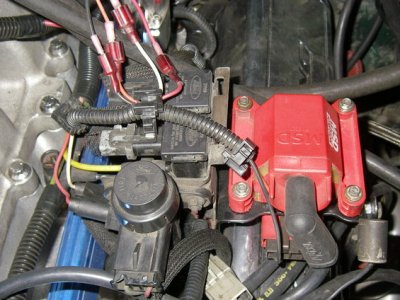
Air Injection (AIR), Secondary Air Injection; Pump (Smog Pump), Thermactor Air Bypass (TAB) & Thermactor Air Diverter (TAD) Solenoids; Diverter, Check & Bypass Valves, Cross-Over Tube, etc.
Overview "...And for the fuel that wasn't burned in the combustion chamber, we need extra airflow pumped into the exhaust system. This air with the heat of the exhaust creates further break down of HC, CO, and Nox into CO2, H2O, and N2. The catalytic converter can accept all of the airflow without fear of over heating during cruise. We need hot exhaust gasses to help complete combustion and converter operation. Air is pumped into the converter, but will dump to the atmosphere after several minutes to prevent overheating the converter. The converter is cooled by air passing under the vehicle..." READ MORE ON Strategies - Start / Crank; Cold Start & Warm Up, etc. for an idea of what needs to be working in each phase for background info. Source: by Ryan M (Fireguy50) at fordfuelinjection.com
-------
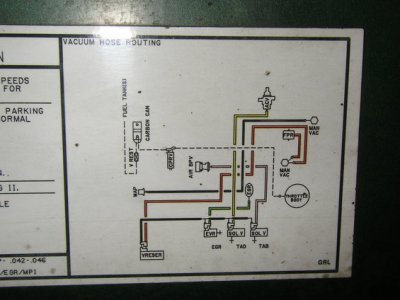
 System Diagram in a 5.0 Source: by Steve83 (Steve, That dirty old truck) at SuperMotors.net
------
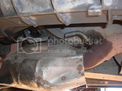
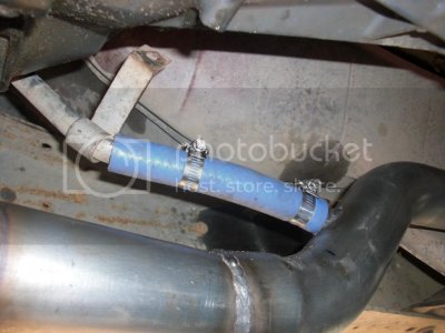
Air Inlet Tube Location pics at Catalytic Converter in an 89 5.0;
w/High Temperature Silicone Hose Source: by rcracerx


 /emoticons/[email protected] 2x" width="20" height="20" /> a friend told me that these symptoms could be caused my a bad cat converter, the more I think about it it seems to make sense it is the factory cat and my old EGR valve was completely clogged with carbon which could be from when a few years back my fuel pressure reg went out and had my truck spewing black liquid out the tail pipe. I could understand how that the bad cat would cause the sputter and backfire but im not seeing how it would be causing the trouble with starting the truck. I am running out of ideas and money at this point I will eventually get to the other 4 injectors but it the meantime is it possible that a bad cat converter can cause these symptoms? One last thing to keep in mind like I said the truck drove home from the shop fine, well maybe 2 or 3 times since then when working on it I would start it and it would seem normal for about 5 mins then it would go back to same thing. Also when I say it is hard to start it takes up to a min of turning over before it starts most of the time, but after I get it started if I shut it off it will start right back up unless it is shut off for like 5 mins then it will take the full min to restart, just something to think about. Thanks so much for the help guys it is always appriciated.


