Yo Gary,
Operation & Diagram; "...The door lock circuit is a common (Ford) polarity-reversing circuit with 2 switches. The switches share the power feed from the battery (always hot). The left (driver's) switch normally holds both motor wires to ground, and the right (passenger's) switch normally holds the motor wires to the left switch wires. When either is operated, it sends one of the wires hot, powering the motors. When operated the other way, the polarity is reversed, reversing the motors' direction. Neither switch is a "master" because neither will work if the other is in the opposite position. Note that the driver's lock motor is not connected to the driver's lock switch..."
PINPOINT TEST A: ONE DOOR LOCK INOPERATIVE
A1 CHECK OPERATION OF SUSPECT DOOR LOCK
- Manually operate inoperative door lock.
- Check for binding or stuck condition.
Is lock stuck or binding?
Yes
No
REFER to
Lock CylinderLubricant in the Lubrication portion of this section. SERVICE as required.
GO to
A2.
A2 CHECK SUSPECT POWER DOOR LOCK ACTUATOR LOCK OPERATION
- Gain access to suspect power door lock actuator. Refer to Actuator, Power Door Lock, in the Removal and Installation portion of this section.
- Disconnect power door lock actuator.
- Using a test lamp connected to a known good ground, check Circuit 117 (PK/BK) at harness connector while actuating door locks in the lock position.
Did test lamp illuminate?
Yes
No
GO to
A3.
SERVICE Circuit 117 (PK/BK) for open circuit. RETEST system.
A3 CHECK POWER DOOR LOCK ACTUATOR FOR UNLOCK OPERATION
- Remove test lamp from Circuit 117 (PK/BK) and connect it to Circuit 118 (PK/O).
- Actuate switch in the unlock position.
Did test lamp illuminate?
Yes
No
GO to
A4.
SERVICE Circuit 118 (PK/O) for open circuit. RETEST system.
A4 CHECK POWER DOOR LOCK ACTUATOR
- Using two 10 gauge jumper wires connected to battery positive (+) and negative (-), attach jumpers to actuator connector; reverse polarity for opposite direction.
Did actuator operate correctly?
Yes
No
GO to
A5.
REPLACE power door lock actuator. RETEST system.
A5 CHECK POWER DOOR LOCK ACTUATOR CURRENT DRAW
- Using Rotunda 73 Digital Multimeter 105-R0051 or equivalent, check actuator current draw.
Is current draw 6 amps or less?
Yes
No
Actuator OK. RECONNECT power door lock actuator.
REPLACE power door lock actuator. RETEST system.
PINPOINT TEST B: ALL DOOR LOCKS INOPERATIVE
B1 CHECK SUPPLY TO LOCK SWITCH
- Partially remove left door lock switch.
- Using voltmeter, check Circuit 171 (BK/W), Pin 3 at switch connector for voltage.
Is battery voltage present?
Yes
No
GO to
B4.
GO to
B2.
B2 CHECK CIRCUIT 171 (BK/W) FOR OPEN
- Disconnect circuit breaker (20A) at primary junction block.
- Disconnect left door lock switch.
- Using an ohmmeter, check resistance of Circuit 171 (BK/W) from door lock switch connector to output side of SEAT/LOCK circuit breaker (20A) cavity.
Is resistance 5 ohms or less?
Yes
No
GO to
B3.
SERVICE Circuit 171 (BK/W) for open. RETEST system.
B3 CHECK CIRCUIT 171 (BK/W) FOR SHORT
- Using ohmmeter connected to a known good ground, connect second lead to Circuit 171 (BK/W) at door lock switch connector.
- Measure resistance.
Is resistance 5 ohms or less?
Yes
No
SERVICE Circuit 171 (BK/W) for short. RETEST system.
REPLACE circuit breaker (20A). RETEST system.
B4 CHECK CIRCUIT 57 (BK)
- Using an ohmmeter connected to a known good ground, connect second lead to Circuit 57 (BK), Pins 1 and 5 at door lock switch connector.
- Measure resistance.
Is resistance 5 ohms or less?
Yes
No
GO to
B5.
SERVICE Circuit 57 (BK) for open. RETEST system.
B5 CHECK DOOR LOCK SWITCH LOCK OUTPUT
- Partially remove RH door lock switch.
- Using a voltmeter, check Circuit 117 (PK/BK) at switch connector Pin 4 for voltage as switch is actuated to the lock position.
Is battery voltage present?
Yes
No
GO to
B6.
REPLACE RH door lock switch. RETEST system.
B6 CHECK DOOR LOCK SWITCH UNLOCK OUTPUT
- Disconnect voltmeter lead from Circuit 117 (PK/BK).
- Connect lead to Circuit 118 (PK/O), Pin 2 at switch connector.
- Measure voltage as switch is actuated to unlock position.
Is battery voltage present?
Yes
No
GO to
B7.
REPLACE RH door lock switch. RETEST system.
B7 CHECK CIRCUIT 117 (PK/BK)
- Gain access to RH door lock actuator. Refer to Actuator, Power Door Lock, in the Removal and Installation portion of this section.
- Disconnect door lock actuator.
- Using a test lamp, check for voltage at Circuit 117 (PK/BK) in harness connector as switch is actuated to the lock position.
Did test lamp illuminate?
Yes
No
SERVICE Circuit 118 (PK/O) for open circuit. RETEST system.
SERVICE Circuit 117 (PK/BK) for open circuit. RETEST system.
Remote Keyless Entry Module Connector C1, F-Series and Bronco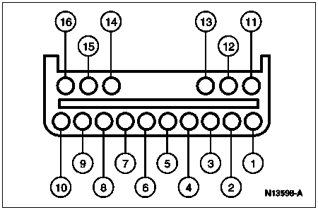
Pin Number
Circuit
Circuit Function
1
54 (LG/Y)
Battery Power
2
—
Not Used
3
—
Not Used
4
—
Not Used
5
875 (BK/LB)
Signal Ground
6
182 (BR/W)
Ignition Switch Ground
7
—
Not Used
8
—
Not Used
9
—
Not Used
10
809 (GY/Y)
Remote Keyless Program B
11
—
Not Used
12
—
Not Used
13
—
Not Used
14
—
Not Used
15
808 (W/Y)
Remote Keyless Program A
16
—
Not Used
Remote Keyless Entry Module Connector C2, F-Series and Bronco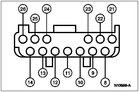
Pin Number
Circuit
Circuit Function
26
1 (DB)
Horn Relay
25
171 (BK/W)
Battery Power
24
14 (BR)
Parklamps Output
23
54 (LG/Y)
Battery Power, Battery Saver Input
22
—
Not Used
21
—
Not Used
14
171 (BK/W)
Battery Power
13
195 (T/W)
Parklamps Input
12
705 (LG/O)
Battery Saver Output
11
705 (LG/O)
Battery Saver Output
10
54 (LG/Y)
Battery Power, Battery Saver Input
9
—
Not Used
8
—
Not Used
Remote Keyless Entry Module Connector C3, F-Series and Bronco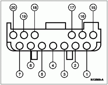
Pin Number
Circuit
Circuit Function
20
—
Not Used
19
53 (BK/LB)
Illuminated Entry Output
18
118 (PK/O)
Unlock All Doors
17
706 (GY)
Door Jamb Switch
16
117 (PK/BK)
Lock All Doors
15
57 (BK)
Ground
7
—
Not Used
6
118 (PK/O)
Unlock All Doors
5
120 (PK/LG)
Door Lock Switch (Unlock)
4
119 (PK/Y)
Door Lock Switch (Lock)
3
163 (R/O)
Driver's Door Unlock
2
117 (PK/BK)
Lock All Doors
1
57 (BK)
Ground
Wiring Diagram for 92-96 (First diagram)
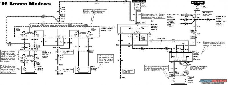
Wiring Diagram for 92-96 w/Connector Locations (second diagram),
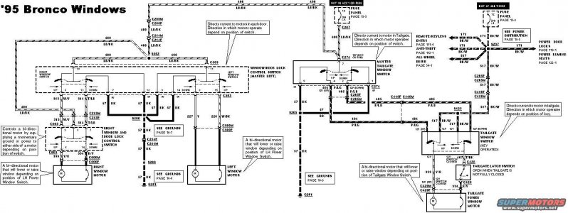
Door Lock And Window Switches Stick In Depressed Position TSB 94-11-18 for 94 Bronco & F Series @
http://www.thedieselstop.com/faq/9497faq/tsb/tsb/files/941118.pdf


