Yo AMK,
WELCOME!
Does your 93 have anti-theft system?
Anti-Theft Overview in 92-96 in E-150-250-350 Vehicles; "...The anti-theft protection system provides two types of vehicle protection. The first is designed to provide the vehicle with protection from unauthorized entry into the passenger compartment and engine compartment (hood opening). The second monitors the status of the ignition switch lock cylinder. If triggered, the system provides both audio and visual alarm signals and disables the starter circuit. The system is controlled by an electronic module. When armed, unauthorized entry into the vehicle is detected by courtesy lamp switches (located in the passenger compartment door jambs), and a hood switch (located on the right cowl surface). In addition, the system triggers an alarm if the ignition switch lock cylinder is forcibly removed from the steering column tube (3514). The system immediately monitors the ignition switch lock cylinder upon removal of the key from the ignition. Once triggered, the system flashes the low beam headlamps, the parking lamps, the alarm indicator, and sounds the horn. In addition, the starter circuit is interrupted until the system is disarmed..." by Ford
- Starter Motor Does Not Crank Engine
|
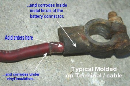
- Loose or corroded battery cable connections.
- Undercharged battery.
- Malfunctioning starter relay.
- Faulty starter motor ground circuit.
- Malfunctioning starter motor.
- Malfunctioning ignition/push-button switch.
|
Following by Ford with additions by the usual suspects;
View attachment 153326
Item Part Number Description
1 3F532 Key Release Lever Spring
2 11572 Ignition Switch
3 7210 Gearshift Lever
4 7A247 Park/Neutral Position Switch or
5 11A152 Clutch Pedal Position Switch
6 11450 Starter Motor Relay
7 11001 Starter Motor
8 11390 Starter Solenoid
9 10655 Battery
B1 check the battery voltage, terminals and cables to ground & alternator for loose or corroded connections.
Voltage; "...a normal battery that is fully charged produces 12.6 volts, not just 12.0 V. (Remember, when measuring battery voltage, everything in the car should be off, or the battery should be disconnected. Voltage measurements are always "no load" measurements unless the battery is being tested for it's performance under load)..." by Gordon
Ground Location,
Frame from Battery pic in a 94 5.8;
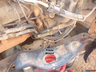
"...Frame ground just inboard of the R spring tower. The black battery wire goes from the front bolt of the engine mount (on the block) to this tab & up to the battery post, where a smaller black wire goes to the core support, providing a continuous ground path between the engine, frame, battery, & body..."
View attachment 184791
Source: by CodysBigBlueBronco (how much $???)
Frame Ground location (Passenger side Cross member above
engine mount)
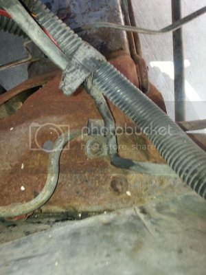
by jowens1126
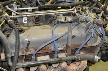
Intake Manifold to Block ******** oassenger side Location pic in a 96 5. by bossind
Inspect STARTER RELAY GROUND; relay located on PASSENGER FENDER LINER, near battery, see Starter Relay pic in a 95
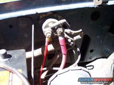
Source: by Shane C. (BigBlue, bigbluebronk)
Check for continuity between relay mounting bracket and clean chassis ground. Rust, grime, paint etc interferes with relay control circuit.
B3 STARTER RELAY FUNCTION
CAUTION: Make sure transmission is in neutral and parking brake is applied.
Connect remote starter switch between battery terminal at starter relay and starter relay S terminal.
Press remote starter switch button or jump it.
Does starter crank engine?
Yes If equipped with an automatic transmission, GO to B4. If equipped with a manual transmission, GO to B7. If relay does not click, GO to B9.
If relay clicks, GO to B10.
B4 With key in START position, check for battery voltage at starter relay S terminal (R/BL). It is the smallest terminal on the relay and the R/BL wire has a push on/pull off connector.
Is battery voltage present?
Yes GO to B9.
NO GO to B5.
B5 BATTERY FEED FROM TRANSMISSION RANGE (TR) SENSOR
With key in START position, check for battery voltage at TR sensor terminal (R/LB).
Is voltage present?
Yes REPAIR open in Circuit 32 (R/LB) between relay and sensor/switch.
NO GO to B6.
B6 BATTERY FEED TO TRANSMISSION RANGE (TR) SENSOR, aka Manual Lever Position Sensor/Transmission Range (TR) Sensor
See pics by jermil01 @
1992 Ford Bronco MLPS pictures, videos, and sounds | SuperMotors.net
With key in START position, check for battery voltage at TR sensor terminal (W/PK).
Is voltage present?
Yes CHECK TR sensor switch adjustment. REFER to below note 1
REPLACE sensor/switch, if properly adjjusted
NO REPAIR open in circuit between sensor/switch and starter relay.
B7 BATTERY FEED TO CLUTCH PEDAL POSITION SWITCH
With key in START position, check for battery voltage at CPP switch terminal (R/LB).
Is voltage present?
Yes GO to B8.
No REPAIR open in circuit between ignition switch and CPP switch.
B8 CLUTCH PEDAL POSITION (CPP) SWITCH CONTINUITY
With key in START position and clutch pedal pressed, check for battery voltage at CPP switch terminal (W/PK).
Is voltage present?
Yes REPAIR open in circuit between CPP switch and starter relay.
No REPLACE CPP switch.
B9 STARTER RELAY GROUND
Check for continuity between relay mounting bracket and clean chassis ground.
Is there continuity?
Yes REPLACE starter relay.
No CLEAN ground connection.
B10 BATTERY FEED TO STARTER SOLENOID ATOP STARTER, NOT THE RELAY ON PASSENGER FENDER LINER:
With key/push-button switch in start position, check for battery voltage at starter solenoid S terminal (R/BL).
Is battery voltage present?
Yes GO to B11.
No REPAIR open in Circuit 32 (R/BL) between relay and solenoid.
B11 STARTER SOLENOID ATOP STARTER, NOT THE RELAY ON PASSENGER FENDER LINER:
Check starter solenoid: inspect wire &;
Starter Solenoid
Disconnect battery negative cable.
Using a Rotunda Digital Volt-Ohmmeter 014-00407 or equivalent, check windings of solenoid assembly for continuity as follows:
Check resistance of solenoid pull-in and hold-in windings in series by measuring resistance between motor terminal and solenoid case. Resistance should be approximately 0.95 ohms.
An extremely high resistance reading indicates a break or fault in winding continuity. A very low resistance reading indicates a short or ground in the winding circuit. Either condition is cause for replacement of the solenoid assembly.
Is starter solenoid OK?
Yes REMOVE starter and perform no-load test at parts store.
No REPLACE starter solenoid.
°
Note 1 Transmission Range (TR) Sensor
SPECIAL SERVICE TOOL(S) REQUIRED
Description Tool Number
Transmission Range (TR) Sensor (MLPS) Alignment Tool T92P-70010-AH
Remove nut securing manual control lever (7A256) to transmission range (TR) sensor.
Turn manual control lever to NEUTRAL position.
Loosen two TR sensor retaining bolts.
Align TR sensor slots using Transmission Range (TR) Sensor (MLPS) Alignment Tool T92P-70010-AH.
Tighten retaining bolts to 6-8 Nm (55-75 lb-in) for E40D and to 7-10 Nm (62-89 lb-in) for 4R70W.
Install nut retaining manual control lever to TR sensor. Tighten to 27-38 Nm (20-29 lb-ft) for E4OD and to 30-35 Nm (22-26 lb-ft) for 4R70W.
Or, as bigric wrote, "...You don't need a tool. Just put it in neutral, loosen the bolts, and line up the marks."
Or, Adjustment Info; "...back-probe the MLP line with a volt meter while in Park, and set it to between 4.277 and 4.736 volts (ideally at 4.5065V, right in the middle of the two limits). As a "double-check" afterward, pull the lever down to 1st gear, and again test the MLP voltage; it should be between 0.293 and 1.167 volts, ideally in the middle at 0.73V..."
Source: by SigEpBlue (Steve) at FSB
Pic by ElKabong
□
"STARTER MOTOR SPINS BUT DOESN'T CRANK ENGINE:
Check Starter drive engagement & flywheel.
Inspect flywheel and drive pinion for damage or excessive wear. See image.
Check operation of drive pinion overrunning clutch;
UNUSUAL STARTER MOTOR NOISE DURING STARTER MOTOR OVERRUN
D1 CHECK STARTER MOTOR MOUNTING
Inspect the starter motor mounting.
Check the starter motor mounting bolts for looseness.
Is the starter motor mounted properly?
Yes GO to D2. No REMOUNT or REPLACE the starter motor.
D2 CHECK STARTER DRIVE ENGAGEMENT
Remove the starter motor.
Inspect the starter drive and flywheel for damage. REFER to Pinpoint Test C1.
Are the starter drive and flywheel OK?
Yes CHECK drive pinion overrunning clutch. REFER to Component Tests in the Diagnosis and Testing portion of this section.
No REPLACE as necessary."


