[
yo!
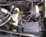
Here is the motor
by a sponsor.....broncograveyard.com
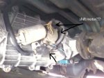
& on Xfer case by Steve
sorry, in reply mode, I can't see your pics and my mnd is gone so I can't recall what they were of....
check;
In fuse box in cab, driver's left knee area..ck Fuse 17
see cover for diagram if different than 17 in my 96 (same for what Ryan cites below)
&
Transfer Case, Borg Warner 1356 Electric Shift Motor Troubleshooting & Repair Source: by Dustin S
by Ryan;
How The Circuit Works
The Electronic Shift Control Module is powered at all times through Circuit Breaker 12 of the Fuse Panel to retain its memory capability. Fuse 18 provides power for the switches and the Electric Shift Motor when the Ignition Switch is in RUN. Fuse 10 provides power for nighttime illumination of the Electronic Shift Control Switch.
When the Electronic Shift Control Switch is placed in the 4x4 or LO position, the Electronic Shift Control Module analyzes information from the Shift Position Sensors to determine their current positions. The Module also analyzes information inputs from the Transfer Case Speed Sensor and the MLP Sensor or Park/Neutral Position Switch. The Electronic Shift Control Module then activates the Transfer Case Motor to produce the desired shift, and the 4x4 Indicator lights up.
http://fordfuelinjection.com/files/1356-1.gif
http://fordfuelinjection.com/files/1356-2.gif
http://fordfuelinjection.com/files/1356-3.gif
Relay..? maybe they're sayin' it's in da Xfer Case Control Module box inside passenger kick panel.. as in what Dustin cites in aforementioned LINK; "...To check if the transfer case motor is actually functioning (because it may be hard to hear it in a noisy shop) attach a voltmeter to A4 and A5. Have someone activate a shift and look for a brief (one second) increase in voltage and listen for the relay to click on, then off..."
more, if you can stand by scribblin'
Borg Warner 1356 Operation & Troubleshooting by Vincent C
especially!;
"Control Module Self-Test
Remove the five-wire connector and the eight-wire connector from the bottom of the electronic control module.
Turn the ignition switch to the RUN position.
Activate the self-test switch located on the module and note the result:
A flashing indicator lamp (approximately one flash per second) indicates that the control module is functioning properly.
A steady indicator lamp indicates that the control module is inoperative and must be replaced.
The Control Module is located behind the instrument panel on the right hand side, behind the wiring harnesses."
lastly, as Ryan describes, "...The Module also analyzes information inputs from the Transfer Case Speed Sensor and the MLP Sensor or Park/Neutral Position Switch..You have the MLPS sensor which is prone to water intrusion; have you run thru a lake or big puddle recently?
VSS would cause other rproblems...such as an ABS light, Cruise control probs and PSOM problems


