4 Wheel drive system dead!

Disclaimer: Links on this page pointing to Amazon, eBay and other sites may include affiliate code. If you click them and make a purchase, we may earn a small commission.

Bronco87autohub

New member
Joined
Nov 6, 2022
Messages
9
Reaction score
3
Location
Calgary Alberta Canada
I have a 1987 Ford Bronco full size, 302, with the Auto Locking hubs. The truck sat for 11 years (yes 11!... kids family took over) Now the 4 wheel drive is dead dead. It has the E67B 7E453-AA shift control module that self tests as 'good'. I've replaced: dash switch, electronic shift motor and the transmission speed sensor and still the system doesn't work. No clicks, humming nothing.
I have read and used Miesk5 circuit diagrams (thank-you sir!) and load tested where I can, both ground and hot (12V) items from the module. All test great, again thank-you Miesk5. Still not a peep out of the system. I don't know how to test for current to the shift motor if the ECM doesn't send any signal. Anyone have any ideas?
I can't source an E67B ECM and suppliers say the F17B 7E453-AA is the same, is that true? Two of the plug ins look different in photos to mine (E67B).
Could it still be the ECM when everything is testing 'good'
 

Tiha

Well-known member
Staff member
Moderator
Joined
Jul 22, 2020
Messages
1,085
Reaction score
1,111
Location
Midwest
Have you taken the shift motor off and manually cycled the transfercase? Make sure it works.

I know you said you are not hearing noises, but manually cycling the transfercase should test the 4x4 and low light I believe.

One of those might trigger the module into waking up.
 

miesk5

96 Bronco 5.0
Staff member
Moderator
Joined
Oct 18, 2005
Messages
9,078
Reaction score
1,035
Location
Floating in the Pacific
Yo Friend,
As Tiha advised and try slapping the shift motor with a rubber (preferred) hammer. Shift motors seem to be #1 fault.

See Nothing happens (dead system). ' see Diagnosis of the Electric Shift 4 X 4
The Ford "Touch Drive" shift-on-the-fly system is currently available on Ranger, Bronco, F-Series and Explorer. Following are the six common concerns most often expressed by customers:

1.Nothing happens (dead system).
2.No range shift.
3.Attempt to shift into 4H from 2H or 4L results in the module clicking and chattering and the system stops in 2H.
4.At start up, the vehicle shifts on its own.
5.Indicator lights don't register the correct information.
6.Shifting on the fly isn't smooth and may require stopping in order to complete the shift.


Figure 21
t41793040.gif


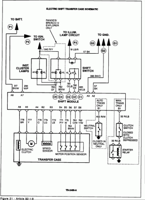
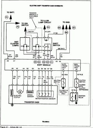
All these conditions can be best understood by taking a close look at a schematic of the electrical system (Figure 21). We will be referring to this schematic throughout this article.

Power In

Power is supplied to the system at 3 points (P1, P2 and P3 in schematic):

P1. This is a direct connection to the battery. This power drives the electric shift control motor and provides current to the instrument cluster lamps. This circuit goes to ground G1.

P2. The electronic shift control module is tied into the ignition circuit. This circuit provides power to the computer and goes to ground G2.

P3. Nighttime illumination is provided by a connection to the vehicle's nighttime illumination circuit, which goes to ground G3.

The electronic shift control module directs power depending on the position of the control switches. You will notice that inputs and outputs to and from the shift module are labeled "A", "B" or "C." "A" circuits are power circuits, "B" circuits are data circuits from sensors and "C" circuits are activating switch and related lamp circuits.

We have already explained the power in circuits "A." The "B" circuits supply data from three sources: The speed sensor, the motor position sensor and either a neutral switch (for automatic transmissions) or a clutch switch (for manual transmissions).

The speed sensor is important because the vehicle must be stopped for a shift into or out of 4L. The shift module won't make the shift if the vehicle is moving. The shift module also won't make a shift to 4L or back unless an automatic transmission is in neutral or the clutch is depressed on a manual transmission.


Figure 20
t41793039.gif


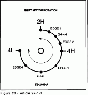
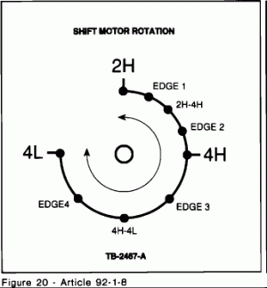
The motor position sensor indicates the position of the shift motor shaft. This shaft turns through approximately 270 degrees and should stop at three indexed points, 2H, 4H and 4L (Figure 20). The shift control module needs to know where the shaft is before making a new shift. When this sensor isn't functioning properly or the motor stops slightly off location, the shift control module may become "confused."

The "C" circuits involve the switches on the vehicle's control panel. When everything is working properly, activating a switch will result in either a shift from 2H to 4H or back, or a shift from 4H to 4L or back. The default operating mode is 2H. This means that in the absence of other instructions, the shift control module will assume that the vehicle should be in 2H. If there is a failure in the system during shifts or engine start up, it will default the vehicle to 2H and permit continued operation.

DIAGNOSIS

With this background, let's diagnose our six problem areas.

Nothing Happens (Dead System)

Figure 22
t41793041.gif

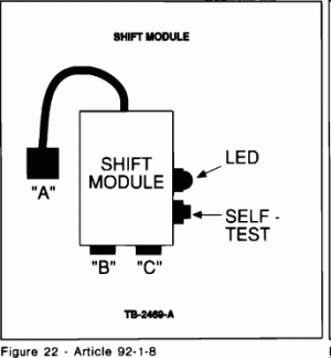
The obvious first step in diagnosing a dead system is to check the power sources, fuses and grounds. If these check out, you should run the shift control module self-test. Figure 22 shows the module with pigtail "A," "B" and "C" attachments. The self-test button and self-test LED are located on the side of the shift control module.

Disconnect the "B" and "C" connectors, turn on the ignition and allow 4 seconds for the module to power up. Then push the self-test button. If the LED doesn't illuminate, the module is dead and must be replaced. If the LED comes on and stays on for 30 seconds, there is an error condition and the module will have to be replaced. If the module is OK the LED will flash 4 times.

This test, however, is not 100 percent accurate. During the test, the vehicle isn't operating, so the shift control module isn't receiving data and initiating shifts. If the unit passes the self-test, it's probably a good module. Go on to check for other probable causes, but don't rule out the module entirely. If your search doesn't turn up any other cause, it may be the module after all. You may have to try replacing the module even though it passed the self-test.

Check Sensors

A logical next step is to check the three sensors with the ignition on. The transmission sensors (manual or automatic) should be closed with the clutch in, or the automatic shift in neutral. The speed sensor should show 225-275 ohms with the vehicle stopped. Check at the module connection.

Figure 20
t41793039.gif

Figure 21
t41793040.gif

Figure 23
t41793042.gif


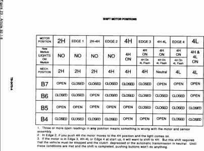
Check both the motor position sensors and the wiring harness at B4, B5, B6 and B7 and the input from B8 (see Figure 21). Make sure the harness is OK first, then check the contacts against the chart in Figure 23. Each valid combination of open and closed switches indicates a different position of the motor. For example, at the 4H position, B7 is closed, B6 is closed, B5 is open and B4 is open. Besides the three main positions (2H, 4H and 4L), intermediate positions are also shown - three between 2H and 4H and three between 4H and 4L (see Figure 20 and the chart in Figure 23). Combinations other than those shown in Figure 23 indicate a defective motor sensor assembly.

Check Transfer Case Motor

To check if the transfer case motor is actually functioning (because it may be hard to hear it in a noisy shop) attach a voltmeter to A4 and A5. Have someone activate a shift and look for a brief (one second) increase in voltage and listen for the relay to click on, then off.

If there is power present, then the control module is trying to run the motor. At this point, unbolt the motor and have someone activate a shift again. If the motor doesn't actually turn, it is malfunctioning and must be replaced.

If there is no power to the motor, check both the power circuits again and the sensors. If there is incorrect sensor data, the module won't power the motor.

Check Shift Switches

If the problem isn't in the sensors or the motor, you should next check the control panel switches. Make this check with the ignition on. Disconnect the "B" and "C" connections to the sensors, so that their data won't confuse the diagnosis. Now check power at the C1 connection at the module. There should be 5 volts coming from the shift control module to the 4H and 4L switches. Check C1, C2, and C3 for short to ground.

You can check the switches themselves by disconnecting C1 and checking continuity across C1 to C2 and C1 to C3. If current passes when the switch buttons are pushed, the switches are OK.

Finally, check for a short between C2 and C3 by bridging between them and activating the 4H and 4L buttons. There are situations where wiring harnesses get crushed in such a way that two wires are crushed together and short, even though there is no short to ground.

Check Lamps
To check the lamps, turn the ignition on and ground C4 and C5. The lamps should light.
END


miesk5

96 Bronco 5.0
Staff member
Moderator
Joined
Oct 18, 2005
Messages
9,078
Reaction score
1,035
Location
Floating in the Pacific
Also because we have a relatively dumb low character limit restriction, here is the rest;
7
1356 Electric Shift Motor Typical Failures & Prevention; "...Most units fail because of water or mud intrusion. Carefully inspect motor boot or protective coverings. Be sure connector seals can keep water and debris out. Check wiring harness and connector. Replace or repair wiring as necessary. After installation, periodically select 4-wheel drive mode to ensure operation when needed..."
Source: by CARDONE

1356 Electric Shift Emergency Shifting; "... I'd thought I'd share some pics for those who may like to know what the t-case 12 volt shift motor does. Or is supposed to do in my case. Just for drill I removed the small motor. You'll only need a 3/8" ratchet wrench and a long 10 mm socket to remove all 6 bolts. Three of them are about 1 1/2" long and goe thru the top right circular head of the motor. The other three bolts are about 3/4" long. One bolts to the bottom flat tang of the motor case itself (ground?) and the other two hold the wire coupler harness in place on the t-case. As I suspected the triangular shaft inside of the t-case was pointing down to indicate 4 High. By merely jiggling the front drive shaft yoke a little bit with one hand, I could very easily move the triangular shaft with my other hand and get it into 2 High; it might be wise to keep the above mentioned ratchet and socket at the ready, as well as a pair of Channel Locks to rotate the shaft if it won't budge by hand..."
Source: by RickyB at FSB

Replacing the shift motor on your BW1356 in a 93 by Froggmann @ Froggmann's 1993 Bronco Page
 
OP
OP
B

Bronco87autohub

New member
Joined
Nov 6, 2022
Messages
9
Reaction score
3
Location
Calgary Alberta Canada
Have you taken the shift motor off and manually cycled the transfercase? Make sure it works.

I know you said you are not hearing noises, but manually cycling the transfercase should test the 4x4 and low light I believe.

One of those might trigger the module into waking up.
I have not tested the shift motor yet as I just went out and replaced it with a new one. That said, you are right that I should see that the motor does engage. Snow just rolled back in here today so it will be a few days before I get back to it as I must work outside. One of the tests I ran involves sending current to the dash lights for continuity, both the Hi (4x4) dash light and the 4Low light, light up with the test so I'm hoping that somewhere else the system is compromised. The only major component I have not replaced is the 4x4 TC module; I'm attempting to source one. Thanks Tiha.
 
OP
OP
B

Bronco87autohub

New member
Joined
Nov 6, 2022
Messages
9
Reaction score
3
Location
Calgary Alberta Canada
Yo Friend,
As Tiha advised and try slapping the shift motor with a rubber (preferred) hammer. Shift motors seem to be #1 fault.

See Nothing happens (dead system). ' see Diagnosis of the Electric Shift 4 X 4
The Ford "Touch Drive" shift-on-the-fly system is currently available on Ranger, Bronco, F-Series and Explorer. Following are the six common concerns most often expressed by customers:

1.Nothing happens (dead system).
2.No range shift.
3.Attempt to shift into 4H from 2H or 4L results in the module clicking and chattering and the system stops in 2H.
4.At start up, the vehicle shifts on its own.
5.Indicator lights don't register the correct information.
6.Shifting on the fly isn't smooth and may require stopping in order to complete the shift.


All these conditions can be best understood by taking a close look at a schematic of the electrical system (Figure 21). We will be referring to this schematic throughout this article.

Power In

Power is supplied to the system at 3 points (P1, P2 and P3 in schematic):

P1. This is a direct connection to the battery. This power drives the electric shift control motor and provides current to the instrument cluster lamps. This circuit goes to ground G1.

P2. The electronic shift control module is tied into the ignition circuit. This circuit provides power to the computer and goes to ground G2.

P3. Nighttime illumination is provided by a connection to the vehicle's nighttime illumination circuit, which goes to ground G3.

The electronic shift control module directs power depending on the position of the control switches. You will notice that inputs and outputs to and from the shift module are labeled "A", "B" or "C." "A" circuits are power circuits, "B" circuits are data circuits from sensors and "C" circuits are activating switch and related lamp circuits.

We have already explained the power in circuits "A." The "B" circuits supply data from three sources: The speed sensor, the motor position sensor and either a neutral switch (for automatic transmissions) or a clutch switch (for manual transmissions).

The speed sensor is important because the vehicle must be stopped for a shift into or out of 4L. The shift module won't make the shift if the vehicle is moving. The shift module also won't make a shift to 4L or back unless an automatic transmission is in neutral or the clutch is depressed on a manual transmission.


The motor position sensor indicates the position of the shift motor shaft. This shaft turns through approximately 270 degrees and should stop at three indexed points, 2H, 4H and 4L (Figure 20). The shift control module needs to know where the shaft is before making a new shift. When this sensor isn't functioning properly or the motor stops slightly off location, the shift control module may become "confused."

The "C" circuits involve the switches on the vehicle's control panel. When everything is working properly, activating a switch will result in either a shift from 2H to 4H or back, or a shift from 4H to 4L or back. The default operating mode is 2H. This means that in the absence of other instructions, the shift control module will assume that the vehicle should be in 2H. If there is a failure in the system during shifts or engine start up, it will default the vehicle to 2H and permit continued operation.

DIAGNOSIS

With this background, let's diagnose our six problem areas.

Nothing Happens (Dead System)


The obvious first step in diagnosing a dead system is to check the power sources, fuses and grounds. If these check out, you should run the shift control module self-test. Figure 22 shows the module with pigtail "A," "B" and "C" attachments. The self-test button and self-test LED are located on the side of the shift control module.

Disconnect the "B" and "C" connectors, turn on the ignition and allow 4 seconds for the module to power up. Then push the self-test button. If the LED doesn't illuminate, the module is dead and must be replaced. If the LED comes on and stays on for 30 seconds, there is an error condition and the module will have to be replaced. If the module is OK the LED will flash 4 times.

This test, however, is not 100 percent accurate. During the test, the vehicle isn't operating, so the shift control module isn't receiving data and initiating shifts. If the unit passes the self-test, it's probably a good module. Go on to check for other probable causes, but don't rule out the module entirely. If your search doesn't turn up any other cause, it may be the module after all. You may have to try replacing the module even though it passed the self-test.

Check Sensors

A logical next step is to check the three sensors with the ignition on. The transmission sensors (manual or automatic) should be closed with the clutch in, or the automatic shift in neutral. The speed sensor should show 225-275 ohms with the vehicle stopped. Check at the module connection.


Check both the motor position sensors and the wiring harness at B4, B5, B6 and B7 and the input from B8 (see Figure 21). Make sure the harness is OK first, then check the contacts against the chart in Figure 23. Each valid combination of open and closed switches indicates a different position of the motor. For example, at the 4H position, B7 is closed, B6 is closed, B5 is open and B4 is open. Besides the three main positions (2H, 4H and 4L), intermediate positions are also shown - three between 2H and 4H and three between 4H and 4L (see Figure 20 and the chart in Figure 23). Combinations other than those shown in Figure 23 indicate a defective motor sensor assembly.

Check Transfer Case Motor

To check if the transfer case motor is actually functioning (because it may be hard to hear it in a noisy shop) attach a voltmeter to A4 and A5. Have someone activate a shift and look for a brief (one second) increase in voltage and listen for the relay to click on, then off.

If there is power present, then the control module is trying to run the motor. At this point, unbolt the motor and have someone activate a shift again. If the motor doesn't actually turn, it is malfunctioning and must be replaced.

If there is no power to the motor, check both the power circuits again and the sensors. If there is incorrect sensor data, the module won't power the motor.

Check Shift Switches

If the problem isn't in the sensors or the motor, you should next check the control panel switches. Make this check with the ignition on. Disconnect the "B" and "C" connections to the sensors, so that their data won't confuse the diagnosis. Now check power at the C1 connection at the module. There should be 5 volts coming from the shift control module to the 4H and 4L switches. Check C1, C2, and C3 for short to ground.

You can check the switches themselves by disconnecting C1 and checking continuity across C1 to C2 and C1 to C3. If current passes when the switch buttons are pushed, the switches are OK.

Finally, check for a short between C2 and C3 by bridging between them and activating the 4H and 4L buttons. There are situations where wiring harnesses get crushed in such a way that two wires are crushed together and short, even though there is no short to ground.

Check Lamps
To check the lamps, turn the ignition on and ground C4 and C5. The lamps should light.
END

Good afternoon Miesk5, I have been following your tests with everything checking out correctly, but there are tests I have not run that you recommend because I am unsure of your instructions. For example, in Check the Switches, to test the dash switch, you say to disconnect B and C; does that mean disconnect the 8 wire (flat) plug, B, and the 5 wire (flat) plug, C, from the module? If this is correct, then to test C1, I connect a red (+) probe of a multimeter wire into the white wire light blue stripe connection on the module (position 1 on the disconnected plug), then the second black multimeter wire goes to ground? On 'volts' setting I should see 5 volts? Not 12v?
How do I then check C1-3 for short to ground... I'm not sure what that means. I have tested C1 to C2 and C1 to C3 for change in resistivity when the switch is pushed and things go from open loop to about 7 ohms each. What you are suggesting is a load test of C1-3? Also, C4 and C5 grounding individually tests the dash lights successfully for Low then Hi 4x4 settings. I am sourcing these tests from Section 16-80 Borg Warner 13-56 Electronic Shift TC chapter PP 16-80-1 to 16-80-11 (Dave Graham scans of the 87 Ford Bronco service manuals)
 
OP
OP
B

Bronco87autohub

New member
Joined
Nov 6, 2022
Messages
9
Reaction score
3
Location
Calgary Alberta Canada
Good afternoon Miesk5, I have been following your tests with everything checking out correctly, but there are tests I have not run that you recommend because I am unsure of your instructions. For example, in Check the Switches, to test the dash switch, you say to disconnect B and C; does that mean disconnect the 8 wire (flat) plug, B, and the 5 wire (flat) plug, C, from the module? If this is correct, then to test C1, I connect a red (+) probe of a multimeter wire into the white wire light blue stripe connection on the module (position 1 on the disconnected plug), then the second black multimeter wire goes to ground? On 'volts' setting I should see 5 volts? Not 12v?
How do I then check C1-3 for short to ground... I'm not sure what that means. I have tested C1 to C2 and C1 to C3 for change in resistivity when the switch is pushed and things go from open loop to about 7 ohms each. What you are suggesting is a load test of C1-3? Also, C4 and C5 grounding individually tests the dash lights successfully for Low then Hi 4x4 settings. I am sourcing these tests from Section 16-80 Borg Warner 13-56 Electronic Shift TC chapter PP 16-80-1 to 16-80-11 (Dave Graham scans of the 87 Ford Bronco service manuals)
Lastly(!), you are saying bridge C2 to C3 (with the ignition on? and 8 wire plugged back in or not?) What should see when I do this and the wiring is good? If wiring is shorted?
Related, maybe, in the circuit diagrams you supply, why are the connects of wires shown as a "Y", is this significant? Rather than the drawing go straight to the schematic item? Thank you.
 
OP
OP
B

Bronco87autohub

New member
Joined
Nov 6, 2022
Messages
9
Reaction score
3
Location
Calgary Alberta Canada
My 1987 Bronco that was dead dead with 4x4 is now working. It was a malfunctioning 4wheel drive control module that was failing. Self testing was coming up 'good' but unbeknownst to me under load it was dead. Thank-you miesk5, your diagrams and comments helped me narrow the problem down to the one item that could not be load tested. Every other circuit tested as working. I located a shift module from an auto wrecker that actually had an Bronco with the auto locking hubs. Thanks everyone.
 

goodO1boydws

Active member
Joined
Apr 22, 2022
Messages
160
Reaction score
148
Location
East Tennessee
Just a suggestion here, but from the previous postings it reads as if the focus has been mostly on electrical issues.

After sitting that long its possible that the hubs themselves may have frozen/rusted into the 2WD mode position so tightly that they can't physically be moved to the 4WD position no matter how hard the rest of a good-working system tries.
Do they use much salt on the roads where you live?
 
OP
OP
B

Bronco87autohub

New member
Joined
Nov 6, 2022
Messages
9
Reaction score
3
Location
Calgary Alberta Canada
Just a suggestion here, but from the previous postings it reads as if the focus has been mostly on electrical issues.

After sitting that long its possible that the hubs themselves may have frozen/rusted into the 2WD mode position so tightly that they can't physically be moved to the 4WD position no matter how hard the rest of a good-working system tries.
Do they use much salt on the roads where you live?
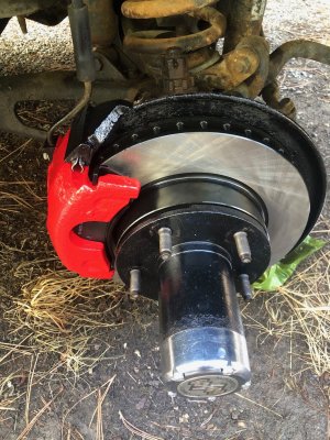
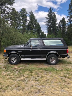
Good point on hubs sitting so long! The very first thing I did before driving the vehicle was to disassemble the hubs and re-grease everything as a ceased bearing was a concern. Cold and snow are the main issues here, not salt, and summers are normally very dry and hot so moisture does not normally cause problems. That said, after 11 years of sitting the gas tank had totally rusted on the inside, tank sender unit looked like it was encrusted with barnacles it was so badly rusted, so the low pressure fuel pump was toast as was the high pressure one under the driver's door. I want to replace injectors but just haven't had the time and the snow only just left here a few weeks ago. When repacking the hubs I replaced the rotors (note the grass in the picture... all work on this baby is done outside). Also a picture of the truck now.
 

Attachments

  • IMG_2855.JPG
    IMG_2855.JPG
    478.1 KB · Views: 2
  • IMG_8153.jpg
    IMG_8153.jpg
    577 KB · Views: 2

goodO1boydws

Active member
Joined
Apr 22, 2022
Messages
160
Reaction score
148
Location
East Tennessee
Like I said, it was just a suggestion-sometimes it's the simplest things that get overlooked.
Now that's a good looking truck!
 

Members online

Forum statistics

Threads
22,621
Messages
136,701
Members
25,282
Latest member
79' Buckin Bronco
Top