1990 Bronco 5.0 will not run with SPOUT connector plugged in.

Disclaimer: Links on this page pointing to Amazon, eBay and other sites may include affiliate code. If you click them and make a purchase, we may earn a small commission.

Hardsun

New member
Joined
Jun 14, 2021
Messages
13
Reaction score
4
Location
Oregon
Hey all, I've been reading through so many posts regarding this issue, with great tech info from MIESK5, Seattle FSB and so many more, and still have not found the answer.
This is my first post here, so be gently, lol.
I have a 1990 Bronco 5.0 manual 4x4.
Note: was running fine before the work.**
My son bought it and it needed a clutch and seals, vehicle had a few oil leaks, including the rear main. In lieu of laying on my back, we opted to pull the engine.
Parts replaced:
Clutch/Pressure plate - flywheel resurfaced and checked. Clutch ***** cyl, clutch master cyl.
Rear main, timing chain/gears, water pump, temp sensor (sending unit)
valve/oil pan gaskets, cracked drivers exhaust manifold.
All put back into the vehicle, primed the oil pump, fuel pump ran injectors pumped,
Fires up on the first try.
Clutch needs a little more bleeding.
While driving up and down the driveway, vehicle stalls out will not start.
No spark, Test came to the Dist pickup, replaced along with ICM while I was there. Nothing. Unplugged SPOUT and it fires right up.
Not sure where to go, looked at the PCM and everything looks good inside. PCM connector plug diagrams I found here didn't match up to the pin location I have on mine (weird??).
Any help or direction would be so appreciated, son wants to drive back to college and I want a reliable truck for him.

Julien.
 

miesk5

96 Bronco 5.0
Staff member
Moderator
Joined
Oct 18, 2005
Messages
9,078
Reaction score
1,035
Location
Floating in the Pacific
Yo Hardsun,
Welcome!
Scroll down in this article;

"The Intermittent No-Spark Ranger​

By Brian Manley
This month's column is about a Ford Ranger one of my students (Drew) said "would only run for about a mile, then die." Since we were in the middle of our electrical and engine performance unit, this vehicle would serve as a perfect troubleshooting opportunity. The story from my student went as follows:
The vehicle began stalling intermittently during driving, but would usually restart right away. Sometimes, however, it would have to sit for a few minutes. Drew had replaced the ignition coil on the advice of a family friend, but the problem persisted. Next, the thick film ignition (TFI) module was replaced with a quality no-name brand from a local parts house. The stalling condition continued. Now, Drew had spent enough time with his friend to decide that the next logical course of action was to replace the entire distributor.
Logical Troubleshooting

Ttfig1.jpg
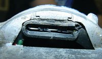
Figure 1 - This is the old profile ignition pickup (PIP) sensor with defective insulation.
Ttfig2.jpg
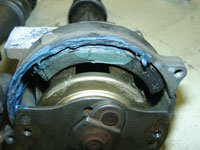
Figure 2 - Believe it or not...Here's the original distributor with silicone around the cap sealing surface.
Ttfig3.jpg
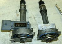
Figure 3 - Here's the old distributor next to the new one, with the transferred ignition module.
Ttfig4.jpg
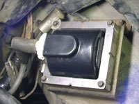
Figure 4 - New ignition coil.
Ttfig5.jpg
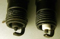
Figure 5 - Both the old and new spark plugs.
Ttfig6.jpg
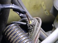
●Figure 6 - The root cause of the problem, which is the shielding wire grounding out the SPOUT signal.

manner.


The sequence I teach is:

  1. Verify the customer concern.
  2. Perform a thorough visual inspection.
  3. Test for the cause of the concern and perform published system testing.
  4. Isolate the root cause and perform the repair.
  5. Verify the repair.
TSBs
Drew found three technical service bulletins (TSBs) pertaining to the ignition system:
  • TFI STALL NO START - TFI MODULE DIAGNOSIS AND SEALING: This bulletin addresses loss of module ground due to salt and moisture entering a module mounting *****.
  • TFI ENGINE NO START/STALL AT IDLE - NEW IGNITION MODULE: This TSB talks about an internal short-circuit in some model TFI modules.
  • DRIVEABILITY CONCERNS - MOIST EEC-IV CONNECTORS: This bulletin asks the tech to check for unsealed EEC-IV connectors and check for moisture or corrosion.
Verifying the Concern, Performing the Visual
Popping the hood on the Ranger revealed the new coil, new distributor cap and new TFI module screwed to the side of the distributor housing. The engine would only run for a few minutes before dying, just as though the key had been turned off. Sure enough, no spark occurred at spark testers when the no-start was present.

Based on the TSB information, I directed Drew to inspect all of the EEC connectors and perform a complete inspection of all pertinent wires and components. We did notice that many of the wiring harnesses had some oil and road grime, and that there was some peeling of the wiring insulation at the EEC-IV module connector, although none of the wires appeared to be shorting.

Now, Drew had already purchased a rebuilt distributor and plopped it down on our workbench. At this point I told Drew about a preliminary test that I learned to determine if the profile ignition pickup (PIP) sensor might be defective. We popped the cap and I pushed my fingernail down into the soft, gooey insulation surrounding the PIP sensor. This has historically been a red flag for techs hunting an ignition fault on Ford vehicles equipped with TFI ignition systems. It seems that the insulation around many PIP sensors breaks down prematurely - a condition that leads to shorting of the wires leading to the TFI ignition module. I always replace a PIP sensor along with a defective ignition module, if it has "soft" insulation.

I liken this to replacing a high energy ignition (HEI) module in an older Delco-Remy distributor. Is it prudent to replace the ignition pickup coil while you're inside this distributor? I always let the customer make the decision, but I lobby for replacement.

Drew was adamant about replacing the distributor, so I helped him through the process of marking the rotor and the housing, then swapping the TFI module from the old distributor to the new one. With this distributor installed, the Ranger now had a new ignition coil, ignition module, cap, rotor and PIP sensor. You can guess what happens next; the stalling condition is still present!

Testing for the Root Cause

At this point I had Drew's full attention, so we systematically walked through a proper diagnosis. A TFI testing worksheet showed a simple and systematic process that eliminates suspect parts and circuits, one-by-one, until the cause for the concern is discovered. The only problem, I explained, was that the engine would usually start right back up, and that made many of the tests ineffective. Still, we verified proper voltages at the coil, resistance across the coil and ground for the distributor.

PIP Signal
I decided to hook my lab scope up to the PIP and spark output (SPOUT) wires to isolate exactly where I was losing my signal to trigger the coil. The PIP signal is generated in the PIP assembly and is an indication of crankshaft position and speed. The PIP signal is fed to both the TFI module and the PCM. Hooking up to this signal with my lab scope would verify the entire distributor assembly. When the engine died and spark disappeared, the square wave produced by the PIP remained intact.

SPOUT Signal
The PIP signal is one of the many inputs processed by the PCM. After receiving all of its sensor inputs, the PCM produces a new signal called the SPOUT. The spark output signal represents the engine operating condition "electronically" and is sent back to the TFI module for comparison with the PIP signal. The TFI module then uses both of these signals to fire the coil at the proper timing interval. While watching the SPOUT signal on my scope, the square wave became jagged and jumpy as the engine sputtered, and then became a flat line before the engine died. Now we had a suspect - the PCM.

A Break
I noticed that when I unplugged the SPOUT connector to check base timing, and let the engine run at base timing, it never died. Unfortunately, this pointed me back to the PCM as a possible cause of my fault. But, when I plugged the SPOUT connector back together, I could make the engine falter and die by gently twisting the harness. Yes! I was sure I had located the fault, and I was right. Look at the figure with the yellow spark output signal wire that is without a section of insulation. This section happens to run through a shield ground that provided a convenient ground source for the SPOUT signal. Just the right bump in the road or vibration from the engine would provide a path of lesser resistance for the SPOUT signal, killing the coil trigger.


The spark plugs had also been through a foul time in this semi-spark engine, so we replaced the entire set.

Repair and Verify
When we exposed the entire distributor harness, I suggested to Drew that he should replace the entire section, but I'm sure there is still just electrical tape between SPOUT and ground."

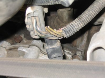
tfi-spout-connectors.jpg
SPOUT Connector Location in an 88 Bronco by Jem270

Here are the 1990 Bronco Pre-Delivery Shop & Electrical & Vacuum Troubleshooting Manuals (EVTM), Partial by member Kingfish999 in Google Drive @ 1990 Ford Truck service manuals - Google Drive
&
1990 Ford Truck Emissions Manual.pdf by Ford via member 90.CaliBronco in Google Drive @ 1990 Ford Truck Emissions Manual.pdf

Suggest you download both for faster scrolling and to use the table of contents index.

1990 Ford Bronco Brochure by Ford via Dezo's Garage @ https://www.xr793.com/wp-content/uploads/2020/07/1990-Ford-Bronco.pdf

Haynes Red Manual for 80-95 Bronco & F Series @ Hanes guide 80-96 bko f series.pdf found by Mrs BroncMom!
Al

 
OP
OP
H

Hardsun

New member
Joined
Jun 14, 2021
Messages
13
Reaction score
4
Location
Oregon
Thanks for the information, I appreciate all the help.
I was looking at it yesterday, pulled the codes, 23- TPS, tested, had a dead spot in it, but in the middle. Other than that it was in range. I replaced, but didn't think it would fix my not start with SPOUT in, it didn't. Also code 41 O2 right side lean, looking into that today.
After originally putting the vehicle back together and driving a few days, I thought the ignition cyl key switch felt sticky, I replaced that, and now the engine starts with the SPOUT connector in, but barely runs, with no response to throttle. I don't think it's the injectors, fuel pump, or fuel pressure (haven't checked pressure yet), but it just doesn't seem logical if they were bad, that they would operate fine with the spout out.
I think I'm going to look at the column switch for proper voltage, any idea what it should be?
Also thanks for the pictures, where the SPOUT was zip tied the wire was bent back, i'll check that today too. Pulling codes again as well.
 

miesk5

96 Bronco 5.0
Staff member
Moderator
Joined
Oct 18, 2005
Messages
9,078
Reaction score
1,035
Location
Floating in the Pacific
Yo,
DTC 41 CM HEGO sensor circuit indicates system lean (right side).
KOER No HEGO switching detected always lean (right side).
"A visual inpection of the harness connector should be sufficient to determine its condition. Check connector pins for corrosion or backed-out terminals.
What the definition of the code means is that the computer can't find the sensor so it is running the engine on default."
"The engine is seeing a lean condition being monitored by the HO2S, and is adding extra fuel. It's a common misconception that a rich or lean O2 code means that an O2 sensor is bad, when actually the O2 sensor is fine and there is either a wiring issue or a mechanical issue. With a lack of other codes I'm inclined to think its either a vacuum leak (if you say it started around the time you replaced injectors I'm really inclined to think this, get a can of starting fluid and spray round the base of the plenum, all the vacuum connections, ect, listen for rpm changes, a short/open in the HO2S wiring." by reese

"tested the O2 sensor to see what it was doing. I tested it right at the computer to make sure all the wiring was good. With the engine warm, I started it up, and the sensor was doing exactly what it was suppossed to do, bouncing between about .1 to .8 volts. But after about a minute or two, it went full rich. The reading stayed around .9 volts, and the idle went up a bit. And the exhaust started stinking, too. The only way to correct this was to pull a vacuum line, and the O2 readings would start varying as normal, and the exhaust would smell clean (of course the idle went high as well). I'm going to swap back in the old injectors to see what happens. Maybe there's something wrong with the new ones. FIND might be right about my injectors." by extreme exploder

TSB 91-12-11 Catalytic Converter Diagnosis
Publication Date: JUNE 12, 1991
LIGHT TRUCK: 1986-91 BRONCO, ECONOLINE, F-150-350 SERIES
1988-91 F SUPER DUTY, F47
ISSUE: Lack of power or a no start condition may be diagnosed as an exhaust restriction caused by a plugged catalytic converter. A plugged catalytic converter (internal deterioration) is usually caused by abnormal engine operation.

ACTION: Diagnose the catalytic converter to confirm internal failure. Refer to the Catalyst and Exhaust System Diagnostic Section, in the Engine/Emissions Diagnostic Shop Manual and the following procedures for service details.

SERVICE PROCEDURE
1. Lack of proper HEGO operation may cause, or be the result of a rich or lean fuel condition, which could cause additional heat in the catalyst. Perform self test KOEO and KOER, service any codes.
NOTE: IF TWO DIGIT CODES 41, 42, 85 OR THREE DIGIT CODES 171, 172, 173, 179, 181, 182, 183 AND 565 ARE RECIEVED, CHECK FOR PROPER HEGO GROUND.
If the HEGO ground is good, the following areas may be at fault:
  • Ignition Coil
  • Distributor Cap
  • Distributor Rotor
  • Fouled Spark Plug
  • Spark Plug Wires
  • Air Filter
  • Stuck Open Injector
  • Fuel Contamination Engine OIL
  • Manifold Leaks Intake/Exhaust
  • Fuel Pressure
  • Poor Power Ground
  • Engine Not At Normal Operating Temperature
  • HEGO Sensor
2. Spark timing that is ******** from specification may increase exhaust gas temperature and shorten catalyst life. Refer to the following procedure for service details.
a. Check spark timing. Check base timing with spout disconnected. Set base timing to the specification on the vehicle emission decal.
b. Check computed timing with spout connected.
NOTE: COMPUTED TIMING IS EQUAL TO BASE TIMING PLUS 20° BTDC ± 3°.
3. Misfiring spark plugs may cause an unburned fuel air mixture to pass through the catalyst, which could cause higher than normal catalyst temperatures. Refer to the following procedure for service details. Check secondary ignition, hook the vehicle up to an engine analyzer and check for a secondary ignition misfire.
NOTE: SERVICE ANY ITEM THAT IS NOT PERFORMING AT PROPER SPECIFICATIONS BEFORE CONTINUING.
4. Fuel pressure that is too high may cause rich air fuel mixtures to pass through the catalyst which could cause higher than normal catalyst temperatures. Refer to the following procedure for service details.
a. Check fuel pressure, install fuel pressure gauge, start and run the engine at idle. Fuel pressures between 28 and 34 PSI are typical (4.9L typically is 15 PSI higher).
b. Disconnect the vacuum line going to the fuel pressure regulator. Fuel pressure typically jumps to 40 PSI ± 3 PSI (4.9L typically is 15 PSI higher). Visually inspect vacuum line for raw fuel.
NOTE: FUEL PRESSURES ABOVE THESE VALUES SHOULD BE CORRECTED. HOWEVER, THIS MAY NOT BE THE CAUSE OF THE CONCERN. SERVICE AS NECESSARY.
5. Throttle plates in the throttle body not returning to the proper closed position may cause excessive catalyst temperatures during downhill grades. Refer to the following procedure for service details. Visually inspect the throttle body and linkage for:
  • Binding or sticking throttle linkage.
  • Tight speed control linkage or cable.
  • Vacuum line interference.
  • Electrical harness interference.
NOTE: AFTERMARKET GOVERNORS, THROTTLE LINKAGE AND CABLES ASSOCIATED WITH POWER TAKE-OFF UNITS, MAY ALSO INTERFERE WITH PROPER THROTTLE RETURN. SERVICE AS NECESSARY.
6. It is extremely important that all systems related to the engine and emission systems operate properly.
a. Visually inspect the engine compartment to make sure all vacuum hoses and spark plug wires are properly routed and securely connected.
b. Inspect all wiring harnesses and connectors for insulation damage, burned, overheated, loose or broken conditions.
c. Verify proper operation of the thermactor system. Thermactor systems that fail to dump thermactor air to the atmosphere properly or at the correct time can cause high catalyst temperatures.
d. Visually inspect thermactor system for damaged or kinked hoses and perform a function test on following components: air control valve, check valve, silencer, filter and the air bypass solenoid.
e. Verify proper operation of the engine cooling system thermostat."
 

chrlsful

Active member
Joined
Oct 13, 2009
Messages
432
Reaction score
218
Location
S. Amherst, MA 01002-1827
this may B the worse era of automotive technology (move frm old sys to new) and the ign system the worse. I like to "go ahead" or "back" (usually back) altho a more knowledgable friend swears by SOME of these prts (TFI to fire points!?!). Anyway I like the ol coil, DSII dizzy, hei 4 pin or blue strain relief brain as a dependable, peppy, sourcable system. If the racers use'em I can too...
 
OP
OP
H

Hardsun

New member
Joined
Jun 14, 2021
Messages
13
Reaction score
4
Location
Oregon
Put some time into it yesterday, Father's day.
I remember thinking the ignition lock cyl seemed sticky and wanted to replace it anyways, so I replace it and it started with the SPOUT connector in.
Terrible rough stumbling, with no response to throttle. Smelled like it was running rich. Pulled codes and found DTC 41 O2 sensor show running lean, so that made sense with the stumbling engine and no throttle response ( I should say, made it worse). Heater voltage was proper, was going to check voltage output, but figured I would unplug the O2 up by the starter solenoid connector and make the PCM run in open loop. Truck with SPOUT connector in, O2 disconnected, fired right up and ran fine. I'll be putting an O2 in it today.
 
OP
OP
H

Hardsun

New member
Joined
Jun 14, 2021
Messages
13
Reaction score
4
Location
Oregon
Stumped, put O2 sensor in and vehicle would not run with SPOUT in again.
Throwing DTC 25 knock sensor?? Not sure where to go with this a this point.
 
OP
OP
H

Hardsun

New member
Joined
Jun 14, 2021
Messages
13
Reaction score
4
Location
Oregon
After warming engine up with SPOUT connector out, I put the SPOUT connector in and it fired up, running rich, then suddenly cleared up and ran fine. Pulled codes, and DTC 25 knock sensor was the only code KOER??
At what point do you think the PCM is the issue??
 

Tiha

Well-known member
Staff member
Moderator
Joined
Jul 22, 2020
Messages
1,085
Reaction score
1,111
Location
Midwest
Have you tried a knock sensor? I don't see where you have, or the wiring to it?

Knock sensor will lower timing. Which is confusing I know but I was thinking pulling the spout connector ignores things like the Knock sensor and O2 sensors and ECT to set base timing.
Once you put the SPOUT back in, then the computer takes over and starts controlling timing based on all the information available from the sensors.

I am not sure I would blame the PCM yet, it seems to be giving you codes and the codes have changed as you have replaced parts and made progress.
 

miesk5

96 Bronco 5.0
Staff member
Moderator
Joined
Oct 18, 2005
Messages
9,078
Reaction score
1,035
Location
Floating in the Pacific
After warming engine up with SPOUT connector out, I put the SPOUT connector in and it fired up, running rich, then suddenly cleared up and ran fine. Pulled codes, and DTC 25 knock sensor was the only code KOER??
At what point do you think the PCM is the issue??
Yo H,
DTC 25 Knock Sensor not tested (KOER); ignore if not pinging
Knock not sensed during dynamic test.
Key On Engine Off MAF sensor was greater than 0.7 volts with engine off.

Common PCM Failure Symptoms
it could be sending the signal to the fuel pump relay to turn the fuel pumps on; One easy test for this is: without the key in ignition, bump the starter over @ the starter relay using a screwdriver. If it is the EEC relay, the truck will start without the key in the ignition..."
Source: by sackman9975

OR, the fuel pump runs continuously when key is in the on position and engine is off.
With No Codes;
Starts, but doesn't run;
an improperly-balanced fuel-to-air ratio
timing is off

Sudden Loss of Gas Mileage.
Failed Emissions Test but no codes. (See below)
Engine Stutters or Stalls.
Erratic or Random Shifting.
You're Receiving a PCM-Related Error Code.

No Codes? By Ryan M
The famous No Code situation that people describe usually ends up being user error. Not that I blame anyone for not getting codes, but the Ford computer outlasts everything else on a vehicle from bumper to bumper. So PLEASE read how to perform a Self-Test and getting Trouble-Codes before tearing the vehicle apart. Replacing computers more than once on a vehicle is not an acceptable repair, other problems exist in that vehicle. Most No Code situations are caused by wiring problems. I have created a list of things to check. Hopefully you can get this sorted out with out burning up computers or beating your head against a wall.
•Check Battery voltage, must be above 10.5 volts.
•Replace battery if not.
•Check battery connections, corrosion, ground faults, and wiring.
• Fix all wiring.
•Check alternator output, must be between 13.5 and 14.5 volts.
•Replace Alternator if not.
•Any recent voltage irregularities from electrical charging system can cause failures.
•Replace alternator and any damaged circuits, wiring, and components.
•Check fusible links on Starter Solenoid if equipped.
•Check fuses and surge protection diode in under hood Power Distribution Box.
•Replace any fuses, diodes, and links if needed.
•Check EEC relay, must show battery voltage when engaged.
•Replace relay and damaged wiring if not.
•Make sure pin 30 on the computer is hooked up correctly.
•Manual transmission computers need to sense SIG-RTN on pin 30 when in neutral.
•Automatic transmission computers need to sense Ground on pin 30 when in neutral.
•Electronicly controled automatic computers need an operational Manual Lever Position Sensor (MLPS)
•Check aftermarket devices like alarm system connected to engine or computer components.
•Restore engine and computer system to original configuration.
•Check aftermarket computer chips and other plug in controls.
•Any chips or controls that impede basic engine and computer function need to be removed.
•Restore computer and harness to original configuration.
•Disconnect computer and inspect for damaged or pushed out pins, corrosion, loose wires.
•Replace computer if visually damaged, repair any damaged pins in harness.
•Visually inspect the ENTIRE engine and computer wiring harness and connections for corrosion, ground faults, shorts, physical damage, and general condition.
•FIX ANY & ALL PROBLEMS!
•Check Self-Test Input circuit on Pin 48 at computer harness for shorts to ground."

Here are some PCM KILLER perpetrators and other causes:
Smell around the PCM. If it smells like dead fish, it's bad.
Look for PCM printed circuit board burn marks around leaking capacitors, resistors.
For example, see Old leaky capacitors in swapped EEC and no more codes by jowens1126
Water damage from cowl leaks, ESPECIALLY if you you have wet carpet or mat near driver kick panel; or on PCM Connector due to a bad hood seal near cowl panel, viewable with hood up.
Corrosion or damage due to moisture is one of the main reasons for failure. Corrosion can enter through the wiring harness and moisture can enter by a failure in the seals in the PCM itself. This happens over a period of time (5 to 10 years) due to exposure to the elements.
The alternator could be generating an AC voltage spike due to bad diode(s) or supply Voltage Overloads.
I recommend bench-testing the alternator for voltage output and AC voltage ripple.
Thermal stress due to excessive heat and excessive vibration that causes sensitive parts to fail.
Bronco was jump started on reverse polarity.
Connector pin damage or corrosion,
Other Internals:
broken tracks,
cold solder joints,
short circuit,
thermal stress due to excessive heat and excessive vibration that causes sensitive parts to fail,
Bad Intel 8061 chip or bad Intel 8361 memory chip,
Bad Internal Voltage Regulator, see Wayback Machine by Fireguy50 (Ryan M)
 
OP
OP
H

Hardsun

New member
Joined
Jun 14, 2021
Messages
13
Reaction score
4
Location
Oregon
I appreciate the feedback.
DTC 25 Knock Sensor not tested (KOER); ignore if not pinging.
The vehicle is not pinging, but, I get what you're saying Tiha. The knock sensor is at the way back by the fire wall, tried to disconnect it, but couldn't quite get it.
I'll try again today.
The interesting thing is the smell of gas, the engine really seems to be running rich when the SPOUT is in. I'm trying to figure out what sensors would affect this. Per Tiha's info, it makes sense to check the knock. I gave it the old school test, had the engine running with SPOUT in and hooked up the timing light, tapped the intake manifold by the sensor, but to reaction to the timing.
I'll keep posting as I go.
Thanks again.
 

miesk5

96 Bronco 5.0
Staff member
Moderator
Joined
Oct 18, 2005
Messages
9,078
Reaction score
1,035
Location
Floating in the Pacific
I appreciate the feedback.
DTC 25 Knock Sensor not tested (KOER); ignore if not pinging.
The vehicle is not pinging, but, I get what you're saying Tiha. The knock sensor is at the way back by the fire wall, tried to disconnect it, but couldn't quite get it.
I'll try again today.
The interesting thing is the smell of gas, the engine really seems to be running rich when the SPOUT is in. I'm trying to figure out what sensors would affect this. Per Tiha's info, it makes sense to check the knock. I gave it the old school test, had the engine running with SPOUT in and hooked up the timing light, tapped the intake manifold by the sensor, but to reaction to the timing.
I'll keep posting as I go.
Thanks again.
Yo,
Find the source of that rich smell. Any exhaust system leaks or rusted pipes, etc from exhaust manifold to tailpipe? Beware of carbon monoxide!
Black Exhaust Smoke is an indication of rich fuel condition.

Fuel Injectors: A leaking or dripping fuel injector will cause a rich fuel condition.

Fuel Pressure Regulator: A stuck closed fuel pressure regulator will cause a rich fuel condition.

Fuel Return: A restricted fuel return line will cause a rich fuel condition.

Plugged fuel filter, air filter, spark plug condition/wrong reach or vacuum leaks.

Any leaks in fuel lines or tank, evap valve atop tank, evaporative system, fuel filter, throttle body/ gasket loose, fuel rails/injectors,?
Gas Cap loose
Excessively rich idle caused by an incorrect MAP Sensor calibration
High exhaust back pressure due to plugged cat/muffler,
EGR pipe rusted. Need to verify this
Exhaust manifold to cylinder head leaks can cause an oxygen sensor (in closed loop) to read lean which in turn causes the EECIV to add more fuel.
 
OP
OP
H

Hardsun

New member
Joined
Jun 14, 2021
Messages
13
Reaction score
4
Location
Oregon
Great info, what is driving me crazy is with the SPOUT out, it runs well, no rich smell, injectors appear to be running correctly. I hear the fuel pump turn on with or with out the SPOUT in or out.
It does have an intermittent stumble with SPOUT in.
No check engine light.

What sensors would tell the computer to run rich?
I will go through the above check list tonight. I appreciate the help.
 

Tiha

Well-known member
Staff member
Moderator
Joined
Jul 22, 2020
Messages
1,085
Reaction score
1,111
Location
Midwest
Miesk made some great points. Any exhaust leaks ahead of the O2 sensor will or can affect it.

Off the top of my head,
Rich can come from
Engine coolant temp.
Map sensor
fuel pump/ pressure regulator.

rich is of course un burnt fuel, like a cylinder missing.
I suppose it could be bad lifters? Not allowing enough air in the cylinder.

Not sure if an open EGR would make it rich, I think it does because there is not enough oxygen to properly burn the fuel. Easy check, loosen it and slip a quarter behind it for testing.

Will the engine rev with spout out? Or in? Could you drive it down the road? (A plugged exhaust will often act like a plugged fuel filter, you can run high rpms for long)

I had an engine that had like 240K on it. It would not start in the cold. Below like 30 degrees. So it sat all winter. Figured fine the engine is junk finally. After finally digging into it turns out that the E3 spark plugs that were highly recommended by a friend were the problem. For all their claims they would not ignite the fuel in the cold weather.

Back to factory plugs and it was a new truck again. Just goes to show the stupidest things, stuff you never would have imagined can trip you up.
 
OP
OP
H

Hardsun

New member
Joined
Jun 14, 2021
Messages
13
Reaction score
4
Location
Oregon
The car will run and throttle up with SPOUT out. I plan on running it up the road like that for a few miles and see what happens.
Voltage on the Map looked good, engine temp sensor fell apart when we were taking it apart, so that has been replaced.
What keeps making me bang my head is, the engine runs well with SPOUT out (i'll up date this after the test drive), so i'm thinking some kind of computer input making the PCM make the motor run out of whack if at all, or the PCM itself.
 
OP
OP
H

Hardsun

New member
Joined
Jun 14, 2021
Messages
13
Reaction score
4
Location
Oregon
Ok, checked the last DTC, 25 knock sensor. ref volt was only 2.9 volts with key on, fully charged battery.
Thoughts?
 

miesk5

96 Bronco 5.0
Staff member
Moderator
Joined
Oct 18, 2005
Messages
9,078
Reaction score
1,035
Location
Floating in the Pacific
Yo,
I forget, did you inspect the harness?
The purpose of the spout connector is to complete the circuit to the distributor to allow the PCM to have timing control.
By removing the spout connector it disables PCM timing control so you can set your base timing by turning the distributor and using a timing light.


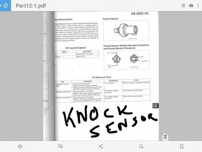
Screenshot_20200510-110708.jpg
 

Tiha

Well-known member
Staff member
Moderator
Joined
Jul 22, 2020
Messages
1,085
Reaction score
1,111
Location
Midwest
Well it looks like the voltage supply is within spec. Of course that doesn't tell us if the sensor is working but it is a start.

Never tried it, but what would happen if you just unplug the thing?
I mean you are already getting the code, Just unplug it and that should send the computer to a default setting. Then see how it runs.
If it runs better I would imagine that means the sensor is bad?
 
OP
OP
H

Hardsun

New member
Joined
Jun 14, 2021
Messages
13
Reaction score
4
Location
Oregon
Update Friday, tried to run the truck up the road with SPOUT out, ran terribly, bucked, back fired, had to feather the throttle just to make it up the road to turn around.

Update, working my way through a trouble shooting guide attached previously.
All grounds are at very little resistance (good ground).
I landed here in the diagnosis: CAPS are my results.(sorry, couldn't find how to change font color.

STEP 7
1 - Disconnect the pin-in-line connector (SPOUT) near the TFI.

2 - Crank the engine

3 - Turn the ignition switch OFF.

4 - If a spark did occur, (IT DID) check the PIP and ignition ground wires for continuity (CONTINUITY FROM TFI TO EEC PLUG GOOD). If okay, the problem is not in the ignition system.

5 - If no spark occurs, check the voltage at the positive (+) terminal of the ignition coil with the ignition switch in RUN.

6 - If the reading is not within battery voltage, check for a worn or damaged ignition switch.

7 - If the reading is within battery voltage, check for faults in the wiring between the coil and TFI module terminal No. 2 or any additional wiring or components connected to that circuit.

NEXT I THOUGHT I WOULD CHECK THIS:

Spark Timing Advance Test #8

Spark timing advance is controlled by the EEC system. This procedure checks the capability of the ignition module to receive the spark timing command from the EEC module. The use of a volt/ohmmeter is required.

1 - Turn the ignition switch OFF.

2 -
Disconnect the pin-in-line connector (SPOUT connector) near the TFI module.

3 - Start the engine and measure the voltage, at idle, from the SPOUT connector to the distributor base (I'M READING THIS, AS MEASUREMENT IS TAKEN FROM SPOUT CONNECTOR GOING TO DISTRIBUTOR, READING 4.8v.. The reading should equal battery voltage.

4 - If the result is okay, the problem lies within the EEC-IV system.

5 - If the result was not satisfactory, separate the wiring harness connector from the ignition module. Check for damage, corrosion or dirt. Service as necessary.

6 -THIS ONE THROWS ME FOR A LOOP. IF THE HARNESS IS DISCONNECTED PIN 1 AND SPOUT WILL NEVER TOUCH???) Measure the resistance between terminal No. 1 and the pin-in-line connector. This test is done at the ignition module connector only. The reading should be less than 1 ohms.

7 - If the reading is okay, replace the TFI module.

8 - If the result was not satisfactory, service the wiring between the pin inline connector and the TFI connector.

PER STEP 7 ABOVE: the problem is not in the ignition system.
What direction does that point me to??
Any help is appreciated, thanks.

Also posted this on FSB, just trying to get help.
 

Members online

No members online now.

Forum statistics

Threads
22,621
Messages
136,701
Members
25,282
Latest member
79' Buckin Bronco
Top