1989 2 Wire Pig Tail on the Negative Battery terminal

Disclaimer: Links on this page pointing to Amazon, eBay and other sites may include affiliate code. If you click them and make a purchase, we may earn a small commission.

SlimShady

New member
Joined
Mar 3, 2016
Messages
3
Reaction score
0
Location
Louisiana
Hello Y'all,

I have a 1989 Ford Bronco 351 Windsor that my kid used as a mudder.

I replaced the negative battery cable and spliced original pigtail coupler on to new cable.

Trunk started afterwards but sometimes would not start after being driven. Now truck will not start and unplugging coupler changes behavior of starter.

Plugged in, starter runs but motor will not fire.  Also the 2 wire get hot.

Un plugged and truck acts like battery is weak.

What is the purpose of the wires?  Did I manage to wire in reverse order?  What did I fry??

Thank you in advance for any information you can give me.

Not found on road dead, but Found On Rednecks Driveway..  Needs to move!!

 
Last edited by a moderator:

Rons beast

Active member
Joined
Dec 13, 2007
Messages
1,537
Reaction score
14
Location
Florida..in my mind , sitting on the beach
Hey Slim , Welcome

I'm a bit confused, but tell me if I have this correct.

You spliced the pigtail on the new battery ground cable to the same wire the old one was attached to. Correct?

Now when the pig tail wire is connected the engine will crank...but not fire. Correct?

If the engine is cranked with the pigtail unplugged (?) the 2 wire...( not sure what that is) gets hot.

The pigtail from the negative cable is to go to body and chassis grounds.  I'm thinking the grounds may be corroded and /or the engine block end of the negative cable is not making a good connection.  ( Tight doesn't mean the connection is good)  The end of the cable and the engine block have to have good clean metal and no oils on them.

The wires getting hot when the engine is cranked, tell me the battery has the power but the circuit has high resistance. This comes from rusty or poor connections.

I would go back over the cable connections. You may also have to replace some of the old body and chassis ground wires.  If they are too hard to get to you can always run new ones to a clean connection on the fender and frame.  Use a #6 gauge wire minimum.

Good Luck


Seabronc

New member
Joined
May 22, 2004
Messages
7,315
Reaction score
35
Location
North of NYC
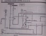
That is a connection for the computer.

However, your problem sounds like the the main battery ground cable connection is bad and when you are making the ground via the two small wires. thus the wires get hot because of the high start current.  I would check the entire battery to engine block and chassis cable.  Disconnect at each connection, clean the contact surfaces and reconnect.  Also, while the cable is disconnected inspect the cable lug to cable connection for any corrosion.  If there is corrosion replace the cable.

:)>-

89EEC 001.jpg

 
Last edited by a moderator:
OP
OP
S

SlimShady

New member
Joined
Mar 3, 2016
Messages
3
Reaction score
0
Location
Louisiana
Guy's thank you for the replies.

To clarify,

Original negative battery cable has a contact to the frame and the block, along with a 2 wire connector to wiring harness in front of battery.

I replaced negative battery cable.  I could not find a replacement with same connector, so i cut old connector off of original and spliced on to new cable.

After which truck would start and run but never driven far, kid in college (LSU)

After awhile If you drove it say to get gas, 50/50 chance it would restart.  Wait 10 minutes and it would start but felt really labored.

During time where it would not start, if I unplugged connector it would start.

Now I cant get to start, new battery installed.


So re cap at where we now.

Connector connected, starter just spins, no attempt to fire.

Connector unplugged; sounds like weak battery

I am wondering if I accidentally reversed wires on connector and fried something?

I will have to confirm if 2 wire connector gets hot just being plugged in or only during attempted engine start


Thanks again for your assistance!


miesk5

96 Bronco 5.0
Staff member
Moderator
Joined
Oct 18, 2005
Messages
9,078
Reaction score
1,037
Location
Floating in the Pacific
Yo Slim,

I'll just post info that I have for now:

EEC Ground Location pic in an 89; "...Those wires eventually connect back to the EEC case (which is grounded) and the pins on the connector that need to be grounded...but then again every ground connects to each other on a Bronco..." Source: by kf4amu (Will H, The Beast) http://www.supermotors.net/getfile/110836/fullsize/img_0346.jpg

Locations in a 90 from 90 Bronco EVTM; "...G100 LH side of Radiator support; G101 RH side of Radiator support; G102 RH side of Radiator support; G103 LH rear side of engine near knock sensor; G104 LH rear side of engine compartment, near electronic engine control (EEC) module, on the left fender close to the firewall; G105 LH Side of engine; G106 RH fender apron, near voltage regulator; G107 RH fender apron, at starter relay; G108 RH fender apron, at voltage regulator; G109 RH fender apron; G201 LH rear side of I/P (looking at the diagram it is at the bottom of the driver's side dash assembly. Screwed to the bottom edge, just to the left of the steering column. It is the ground for the instrument cluster) MIESK5 NOTE, ALSO G701 is for cluster, speed ctl., heater blower sw., cigar lighter, et., see diagram below; G202 Behind RH cowl panel; G203 RH rear side of radiator support; G204 On steering column; G205 Behind Center of I/P (Dash); near speed control amplifier; G400 LH side of cargo area; near rear light assembly; G401 Below LH side of cargo area; near crossmember; G500 Inside driver's door; near left door speaker"

Source: by BroncoJoe19 (Joe) at Ford Bronco Zone

Some morevgrounds shown in 2 wiring diagrams at http://www.revbase.com/BBBMotor/Wd/DownloadPdf?id=21142 & http://www.revbase.com/BBBMotor/Wd/DownloadPdf?id=21135

Start sys. Diagrams:

http://www.revbase.com/BBBMotor/Wd/DownloadPdf?id=21146

http://www.revbase.com/BBBMotor/Wd/DownloadPdf?id=21147

More diagrams @

http://www.revbase.com/BBBMotor/Wd

Same as by Ford EVTM

***

Engine Wiring diagram by ARRC (same as in Chilton)

http://arrc.ebscohost.com/statics/p5/images/sm/isbn_graphics_complete/8828/chiltonimages/8828/88286w00l.jpg

 
OP
OP
S

SlimShady

New member
Joined
Mar 3, 2016
Messages
3
Reaction score
0
Location
Louisiana
Thank you for all the posts.  Problem was with main ground to block on Negative cable.  Multi use stud (ground, Fuel line bracket..) with 2 nuts had a nice gap between cable and block.

Truck turns over great now.. just won't start.  Haven't checked on if it is fuel or spark yet but I hear gas pump on rail spin up.

Could I have damaged the EEC?


miesk5

96 Bronco 5.0
Staff member
Moderator
Joined
Oct 18, 2005
Messages
9,078
Reaction score
1,037
Location
Floating in the Pacific
Yo,

Good job!

Last to check is the eec due to replacement $.

EECs usually fail due to leaky capacitors.

Capacitor Repair in a 90 5.8

Source: by dolittle (seedpress) at http://www.fullsizebronco.com/forum/7-1980-96-bronco-tech/180518-fuel-pump-runs-but-engine-wont-start.html

"... finally pulled the computer and, sure enough, two of the electrolytic capacitors had leaked. Not only were they shot, but the leaked electrolyte had begun corroding some pins on one of the semiconductors. The computer board is covered with a conformal coating to protect it against moisture and contamination, but the electrolyte had also seeped under or through that coating and discolored the board in places.

First I cut out all three of the electrolytic capacitors, although only two of the three had leaked. Then I tried to clean the spilled electrolyte. To remove the corrosive electrolyte I had to strip off the conformal coating where I saw board discoloration. I tried to clean the affected areas with rubbing alcohol, dilute acetone (used for finger nail polish remover), and WD-40. Also, one logic IC (integrated circuit) had three pins that were corroded by the electrolyte. I tried as best as I could to clean them mechanically.

The two leaking capacitors were 47uF 16V, and the third a 10uF 63 volt. I didn't have these values on hand, but coincidentally I had just bought a hundred 22uFs with a 63V working voltage. So by paralleling two of the 22s I was able to get 44uFs, and in series I got an 11 uf. Electrolytic caps have a wide tolerance range anyway, so I hoped that would be good enough. The one problem was all the original caps were 105 C temperature, whereas my replacements are only 85 C. But my computer is behind the driver's kick panel, instead of in the engine compartment. So, I am hoping it will work, at least for a while.

It was a pain to replace the caps! First, I found it difficult to solder the new, "paralleled" capacitors to the printed circuit board. Then, I wasn't sure how many layers the board had -- it's easy to overheat and ruin underlying layers. Finally, some of the copper pads to which the new caps were being soldered were also very close to fine-pitched copper traces. My finished "repair" is a real mess! But it seems to be working.

http://s873.photobucket.com/user/dolittleproject/media/Bronco/IMG_4531-mod4.jpg.html


Members online

No members online now.

Latest posts

Forum statistics

Threads
22,666
Messages
136,900
Members
25,362
Latest member
Wihill
Top