93 5.0 gauges stoped working and engine now surging

Disclaimer: Links on this page pointing to Amazon, eBay and other sites may include affiliate code. If you click them and make a purchase, we may earn a small commission.

spiritofone420

New member
Joined
Oct 17, 2017
Messages
10
Reaction score
0
Location
Heber/Overgaard, AZ.
1993 Bronco 5.0 4x4. My gauges stopped working and engine is surging. This happened at the same time (alt reads below 0, water 0, oil 0, fuel way past full). This acts like a week fuel pump which would be fine if it weren't for the gauges. The engine idles fine but stumbles under a load. The fuel system, engine, alternator are all new. Hope someone can help. ... Gary

front-plate-1.jpg


miesk5

96 Bronco 5.0
Staff member
Moderator
Joined
Oct 18, 2005
Messages
9,071
Reaction score
1,019
Location
Floating in the Pacific
Yo Gary,

Will be back later or Tuesday with more info.

For now try a Self Test for Diagnostic Trouble Codes (DTC)s by my pal, BroncoJoe19

@ http://broncozone.com/topic/14269-code-reader/?pid=74587&mode=threaded

The engine temperature must be greater than 50° F for the Key On Engine Off (KOEO) Self-Test and greater than 180° F for the Key On Engine Running (KOER) Self-Test.

Run it around to heat the engine up and shift thru all gears including Reverse.

Make sure A/C is off and transmission is in Park (automatic); or in Neutral for a Manual & release clutch.

Then turn off engine, all accessories/lights (close driver's door) , etc.

A helper can assist you by counting the codes. Some use their smart phones to record them.

BEWARE OF FAN, BELTS, PULLEYS, HOT HOSES, IGNITION HIGH TENSION WIRES, AND ENGINE COMPONENTS

Do KOEO test First

Post Code(s) here according to: KOEO & KOER

Or ask local mom and dad parts stores if they will test it for you.

Or purchase a coder reader such as Equus 3145 Innova OBD I Code Reader for Ford EEC IV Engines at Walmart &€ most parts stores.

A vacuum leak is a typical surge perpetrator.

See my vacuum leak test in post #20 @ http://broncozone.com/topic/23994-90-58l-getting-continuous-code-33-and-running-code-44/?p=125535

One way to do a quick check is to grab a vacuum gauge. Bring the engine to normal operating temperature. Connect gauge to the intake manifold tee. BEWARE OF FAN, BELT, PULLEYS & HIT ENGINE.

The vacuum gauge should read between 15 and 22 in-Hg depending upon the engine condition and the altitude at which the test is performed. SUBTRACT ONE INCH FROM THE SPECIFIED READING FOR EVERY 1,000 FEET OF ELEVATION ABOVE SEA LEVEL.

The reading should be quite steady. .

When engine is rapidly accelerated (dotted needle), needle will drop to a low (not to zero) reading. When throttle is suddenly released, the needle will snap back up to a higher than normal figure.

When vacuum leaks are indicated, search out and correct the condition. Excess air leaking into the system will upset the fuel mixture and cause conditions such as rough idle, missing on acceleration, or burned valves. If the leak exists in an accessory unit, such as the power brake, the unit will not function correctly. Or Air Conditioning when in MAX mode may switch to Defrost.

Will work on the gauges later. But here is a wiring diagram, http://www.revbase.com/BBBMotor/Wd/DownloadPdf?id=8639

Check fuse #17 first.

One perp for a blown #17 fuse is Fuse 17 Blown, Short Circuit in TSB 92-22-5 for 92 Bronco & all Light Trucks. The transmission control switch wiring may be misrouted causing a short in the steering column and a blown # 17 fuse. The following symptoms may be associated with this concern; Early shifts, Loss of power, Poor acceleration, 3-4 shift cycling, Transmission control light cycling ON/OFF or inoperative, Transmission control switch inoperative, Rear Anti-Lock Brake System (RABS) electronics (dash lights inoperative, ☆Loss of instrumentation (tach, fuel gauge, etc.),☆ Unable to read Self-Test codes (solid tone only with a code scanner).

Inspect the transmission control switch wiring for damage and repair or replace as necessary. Refer to the following procedure for service details.

1. Remove the steering column cover. Refer to the 1992 Bronco/F-Series Service Manual, Section 11-04B, for the removal procedure.

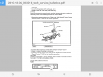
2. Examine the transmission control switch wiring for damage, Figure 1. (I don't have this Figure)

3. Repair or replace the wiring as necessary.

4. Install the steering column cover. Refer to the 1992 Bronco/F-Series Service Manual, Section 11-04B, for the installation procedure.

CAUTION:

DURING REASSEMBLY, ROUTE WIRING AWAY FROM ATTACHING ***** SO AS NOT TO PINCH OR DAMAGE WIRE.

OTHER APPLICABLE ARTICLES: NONE

WARRANTY STATUS:

Eligible Under Bumper To Bumper Warranty Coverage

OPERATION DESCRIPTION TIME

922205A Repair Wiring 0.6 Hrs.

DEALER CODING

BASIC PART NO. CONDITION CODE

15A808 X1

OASIS CODES:

201200, 203200, 204000, 206000, 301000, 501000, 503300, 504000, 614000, 614600

The transmission control switch is at end of shifter stalk.

.

GL!
 
OP
OP
S

spiritofone420

New member
Joined
Oct 17, 2017
Messages
10
Reaction score
0
Location
Heber/Overgaard, AZ.
Thank you for your reply. Just for the record the gauges and the engine happened at the same time. I will get the codes going and post them probably be tomorrow though.

---------

Number 17 fuse is not blown. #17 calls for 10 amp but has a 7.5 and has since I owned it so I will change it, but suspect it is not the problem. (wish it was). Will pull codes tomorrow. As a side note: my key switch has always been questionable. (the mechanical portion at the top of column ).

 
Last edited by a moderator:

miesk5

96 Bronco 5.0
Staff member
Moderator
Joined
Oct 18, 2005
Messages
9,071
Reaction score
1,019
Location
Floating in the Pacific
Yo,

When rotating the key through all positions, such as start; then letting it spring back to run (The ignition key should return from the START position back to the ON position without assistance (spring return)); then off; then to accessory position the movement should feel smooth with no sticking or binding. If it has High Key Efforts such as sticking or binding is encountered, check for the following:

Damaged ignition switch lock cylinder. LUBRICATE ignition switch lock cylinder and CHECK for burrs on key. If effort is still excessive, REPLACE ignition switch lock cylinder.

Steering column shrouds misaligned. ALIGN steering column shroud to fit properly.

Casting/actuator binds, sticks, grabs, with key rotation. If improper fit between casting and actuator exists, REPLACE parts.

If burrs are found on actuator surfaces which contact the casting during key travel, gently FILE these surfaces until smooth. At no time attempt to file teeth of actuator.

If serious burrs are found on casting surface which contact actuator during key travel, REPLACE the casting.

If actuator teeth show excessive wear or are burred, REPLACE actuator.

ASSEMBLE lock housing taking care to thoroughly **** all internal components and CHECK key efforts. If still high, REPLACE lock housing.


Borrow or purchase a vacuum gauge and get some readings. Some parts stores may "loan" you one under a loan a tool program.

 
OP
OP
S

spiritofone420

New member
Joined
Oct 17, 2017
Messages
10
Reaction score
0
Location
Heber/Overgaard, AZ.
OK ... I ran the code gizmo (Actron) and got NO CODES solid light/beep. retried several times with the same results. As for the lock cylinder I will be replacing it but the truck starts fine and idles fine engine rev's fine just gauges don't function and won't pull under load.


miesk5

96 Bronco 5.0
Staff member
Moderator
Joined
Oct 18, 2005
Messages
9,071
Reaction score
1,019
Location
Floating in the Pacific
Yo,

Ok, try the vacuum leak test.

Some no code usual suspects by Ford;
Vacuum leak, see my leak diagnosis
Air filter, is it relatively clean?
Air inlet atop radiator support to filter box and to throttle body; look for obstruction; damaged tubing
Fuel quality; Oxidized fuel often turns darker over time and may even smell sour. You can check stored gasoline by pouring some into a clear glass container and comparing it side-by-side with known fresh gasoline. If your old sample looks noticeably darker than the fresh gas, you have strong evidence the gas has gone bad.
Electrical connectors; inspect at coil, ignition control module, distributor, PCM, etc. especially those with broken locking tabs.

Do you hear any spark knock while it stumbles?

As for the gauges, can you troubleshoot the wiring?

Here is the wiring diagram for the 93,msamr as by Ford;

 http://www.revbase.com/BBBMotor/Wd/DownloadPdf?id=8639

Easy visual check is to inspect Ground G200; G200, Instrument Cluster ground is inside passenger side kick panel 

[SIZE=24.2469px].[/SIZE]

[SIZE=24.2469px]Al[/SIZE]

 
OP
OP
S

spiritofone420

New member
Joined
Oct 17, 2017
Messages
10
Reaction score
0
Location
Heber/Overgaard, AZ.
Another question ...

One perp for a blown #17 fuse is Fuse 17 Blown, Short Circuit in TSB 92-22-5 for 92 Bronco & all Light Trucks. The transmission control switch wiring may be misrouted causing a short in the steering column and a blown # 17 fuse. The following symptoms may be associated with this concern; Early shifts, Loss of power, Poor acceleration, 3-4 shift cycling, Transmission control light cycling ON/OFF or inoperative, Transmission control switch inoperative, Rear Anti-Lock Brake System (RABS) electronics (dash lights inoperative, ☆Loss of instrumentation (tach, fuel gauge, etc.),☆ Unable to read Self-Test codes (solid tone only with a code scanner).
Does this pertain to a '93 or specific to '92? either way I will be checking this system as quite a bit seems to fit. Could you clarify "3-4 shift cycling" I think I know what this refers to, but would like to be sure. ... Thx


miesk5

96 Bronco 5.0
Staff member
Moderator
Joined
Oct 18, 2005
Messages
9,071
Reaction score
1,019
Location
Floating in the Pacific
Yo,

Ford got sloppy about updating the TSBs as planning began to replace the Bronco with the Expedition.  So I would trust the TSB is good for your year.

transmission is cycling between 3rd and 4th

 
OP
OP
S

spiritofone420

New member
Joined
Oct 17, 2017
Messages
10
Reaction score
0
Location
Heber/Overgaard, AZ.
Success!! ... #17 Fuse was the culprit. It showed to be OK with the analog meter BUT coupled with the fact that 1. calls for 10 amp but had a 7.5 amp and 2. after close visual inspect I found a notch in the wire in the fuse itself, meaning that it had not blown completely but enough that it would not pull the amperage needed to run the complete system. Thank you for your help as it would have taken me a long time to figure that one out. ... Gary


miesk5

96 Bronco 5.0
Staff member
Moderator
Joined
Oct 18, 2005
Messages
9,071
Reaction score
1,019
Location
Floating in the Pacific
Yo Gary,

Great that you kept at it!

If the fuse blows again, check the wiring.

Wiring diagram @  http://www.revbase.com/BBBMotor/Wd/DownloadPdf?id=8627

I found the figure showing where the short COULD BE.  SEE attachment below.

Wire to inspect is Tan/White; with engine running, it should havev12 volts DC. 

The wire runs through Connectors; 

C275 Top of steering column, near transmission control switch (C10) Terminal: 03

C202 is @ driver side, rear of engine compartment, in safety (fire) wall (A8) Terminal: 7 In-Line

To EEC PIN 41

...

Check under dash to see if wiring harness is tight against what Ford describes as the Half car beam.  That is the horizontal brace.

...

Transmission Control Switch

Vehicles equipped with E4OD or 4R70W automatic transmissions have transmission control switch (TCS) located on the end of the gearshift lever (7210). Pushing the transmission control switch will either disengage or engage the overdrive function of the automatic transmission. If the transmission control switch has been depressed and OVERDRIVE disengaged, the word OFF will illuminate on the gearshift lever.

...

Shift Lever Replacement; "...To change it, you'll want to drop the steering column. This sounds more difficult than it actually is. There's four nuts that hold the column up. 1/2 head side. Take the plastic housing off, undo the gear select cable, drop the column. There are a couple of plates that hold it in place. Torx head screws hold the plates. Undo those, then the shifter will become loose. Wiggle it free. Install in reverse order. Now, I did not pull the shifter itself while the column was in the truck. So there might be a little more involved if you try to do this while the column is in the truck. If it seems tricky to do so without the column removed completely, then remove it. There's a bolt the attaches the the steering rod to column, shift cable and some wiring to remove.,," 
Source: by sackman9975

Shift Lever & Housing Removal & Installation in a 96 
Source: by Ford via justanswer.com Shift Lever & Housing Removal & Installation in a 96; from 1996 F-150, F-250, F-350 F-Super Duty and Bronco Workshop Manual 
Source: by Ford via thedieselstop.com      
Screenshot_20171021-095358.png

 
Last edited by a moderator:
OP
OP
S

spiritofone420

New member
Joined
Oct 17, 2017
Messages
10
Reaction score
0
Location
Heber/Overgaard, AZ.
Thanks for the info. I will be checking this ... in particular the OverDrive system. The one time I used it I pushed the button and blew-up my first engine. Not that it had anything to do with it but the button has left one of those pictures that won't go away. Will be checking it out. Where can I find more info on that system. (It's operation) ... Thx.


miesk5

96 Bronco 5.0
Staff member
Moderator
Joined
Oct 18, 2005
Messages
9,071
Reaction score
1,019
Location
Floating in the Pacific
Yo Gary,

Section 07-01A: Transmission, Automatic, E4OD

1996 All F-Series and Bronco with E4OD Automatic Transmission Workshop Manual

DESCRIPTION AND OPERATION

Transmission Description

The E4OD transmission is a fully automatic, electronically controlled, four-speed unit with a torque converter clutch. The main operating components of the E4OD transmission include a torque converter clutch, six multiple-disc friction clutches, one band, one sprag one-way clutch and two roller one-way clutches that provide for the desired function of three planetary gear sets.

Transmission gear selection in the (D) range and converter clutch operation is controlled by the powertrain control module (PCM) (12A650). Operating conditions are relayed to powertrain control module by various sensors throughout the vehicle. The powertrain control module compares these conditions with electronically stored parameters and logically determines how the transmission should operate.

A torque converter (7902) couples the engine to the transmission gearset via the input shaft (7017) and the torque converter impeller hub. The impeller hub provides engine rpm to the positive displacement pump. The flow from the pump is proportional to engine rpm, and excess pump capacity is exhausted back to the pump inlet.

The input shaft transfers power into the transmission gearset. The power input is controlled by the application of the torque converter clutch, which is scheduled through the powertrain control module.

The application of the piston plate effectively replaces the hydraulic coupling between the converter cover and the turbine with a mechanical coupling between the converter cover and the turbine hub. This mechanical coupling helps improve fuel economy and wide-open throttle performance by eliminating converter slip.

Transmission shift selection and torque converter clutch operation are controlled by the PCM. They are calibrated to provide the optimal transmission state. This state is commanded to the transmission solenoid body.

In the (D) range, automatic operation of all four gears is possible. The transmission control switch, located on the vehicle's shift lever disables overdrive operation and enables automatic operation through the first three gears. Whenever the ignition switch is turned on, the vehicle will automatically provide overdrive operation regardless of the switch position the last time the vehicle was running.

Manual gear selection is available in the 1 and 2 range. Second gear is commanded when the gearshift selector lever is in the 2 range and when downshifted into the 1 range at speeds above approximately 56 km/h (35 mph) (for diesel 48 km/h [30 mph]). First gear is commanded in the 1 range at start-ups and when downshifted into 1 range below approximately 56 km/h (35 mph) (for diesel 48 km/h [30 mph]). Any reference to intermediate brake drum or direct clutch cylinder are one and the same.

Description: The transmission control switch (TCS) is a momentary contact switch. When the switch is pressed, a signal is sent to the powertrain control module. The powertrain control module then energizes the transmission control indicator lamp and the coast clutch solenoid, applying the coast clutch to provide engine braking and cancels fourth gear operation. The TCIL indicates overdrive cancel mode activated (lamp on), electronic pressure control circuit shorted or monitored sensor failure (lamp flashing).

Sensor: Transmission Control Switch.

Symptoms: No overdrive cancel when switch is cycled.

Diagnostic Trouble Codes: 632, P1780, tested during Key On Engine Off (KOEO) On-Board Diagnostic only.

Actuator: Transmission Control Indicator Lamp.

Symptoms: Failed on — overdrive cancel mode always indicated, no flashing for electronic pressure control circuit shorted. Failed off — overdrive cancel mode never indicated, no flashing for electronic pressure control circuit shorted, also may be due to a bad fuse. Erratic operation (flashing) may be due to a wiring concern.

Diagnostic Trouble Codes: 631, P1779.

..

Automatic Transmission Operation (E4OD and 4R70W) The E4OD and 4R70W transmissions are electronically controlled four speed automatic transmissions with overdrive. Transmission operation is controlled by the Powertrain Control Module (PCM). The PCM will automatically adjust transmission operation to make up for varying conditions. Several sensors located on the engine and transmission such as Throttle Position, Engine Speed, Vehicle Speed and Transmission Temperature are used by the PCM to shift the transmission into a higher or lower gear when required for the best performance and fuel economy. For example, you may notice that the transmission will upshift to a higher gear more quickly when the vehicle is first driven and has not reached normal operating temperature. The PCM also controls the transmission’s Torque Converter Clutch to further raise vehicle performance and fuel economy. The Torque Converter Clutch will engage when the transmission operating temperature and other conditions determined by the PCM have been met. Engagement of the clutch may be noted as a decrease in engine speed after an upshift has completed or when the driver has depressed the throttle while driving at a steady road speed. To help in troubleshooting, the PCM continually performs self-tests on the electronic control system and if any faults are detected, will store them in memory. The Transmission Control Indicator Light (TCIL), which is located on the gearshift lever, may flash steadily if a malfunction has been detected. If the TCIL is flashing, contact your Ford dealer as soon as possible. If this condition persists, damage to the transmission could occur. NOTE: The word “OFF” located on the end of the gearshift lever is the transmission control indicator light (TCIL). Putting Your Vehicle in Gear Your vehicle’s gearshift is on the steering column. The Transmission Control Switch and indicator light are located on the end of the gearshift lever. You can put the gearshift in any of the several positions once you place the gearshift securely into position, gradually release the brake pedal and use the accelerator as necessary.

When to use j (Overdrive) This is the normal driving position. As the vehicle picks up speed, automatic upshifts to second, third and fourth gears will occur when jOverdrive is chosen on the selector and the transmission control switch has not been pressed. The transmission will shift into the correct gear when the right speed is achieved, for the accelerator pedal position you have chosen. When to use Drive You will note that there isn’t a drive position on your gearshift indicator. However, you will find a Transmission Control Switch and an indicator light labeled “Overdrive” located on the end of the gearshift lever. Press this switch and the word “OFF” will illuminate on the shift lever ****. With the word “OFF” illuminated, the transmission will operate in gears one through three. Operating in the Overdrive “OFF” mode gives more engine braking than Overdrive and is useful for descending hills or when towing.

To return the transmission to the normal j Overdrive operation, press the transmission control switch again. The Transmission Control Indicator Light will not be illuminated when Overdrive operation resumes. This switch may be used to select O/D ON or O/D OFF any time the vehicle is being driven. When starting your vehicle, the overdrive system will automatically be in the normal overdrive mode. If the Transmission Control Indicator Light is flashing on and off steadily, a transmission system malfunction was detected. The transmission will operate in a failure management mode and may have harsh engagements, firm shift feel, or abnormal shift schedule. If this condition persists, damage to the transmission could occur. Contact your dealer as soon as possible. When to use 2 (Second) Use 2 (Second) to start-up on slippery roads or to provide additional engine braking on downgrades. This position provides 2 (Second) gear operation only. When to use 1 (Low) Use 1 (Low) to provide maximum engine braking on steep downgrades. Upshifts from 1 (Low) can be made by manually shifting to 2 (Second) or j (Overdrive). Selection of 1 (Low) gear provides only low gear operation from start-up. Selection of 1 (Low) while at higher speeds provides a shift to second gear, and a shift to first gear will occur after the vehicle decelerates to the proper speed.

P (Park) Always come to a complete stop before you shift into P (Park). This position locks the transmission and prevents the rear wheels from turning. To securely latch the gearshift in the P (Park) position, pull it toward you, push it completely counterclockwise against the stop, and then push it toward the instrument panel. The gearshift is securely latched in P (Park) if you cannot rotate it in a clockwise direction without lifting it toward you. WARNING Always set the parking brake fully and make sure that the gearshift is securely latched in P (Park). When the transfer case is in the N (Neutral) position, the engine and transmission are disconnected from the rest of the driveline. Therefore, the vehicle is free to roll even if the automatic transmission is in P (Park) or the manual transmission is in gear.

Forced Downshifts To gain extra acceleration in j Overdrive or Drive (O/D OFF), push the accelerator to the floor. The transmission will automatically downshift to the appropriate gear: third, second or first. Power Braking Increasing the engine speed above idle without vehicle movement (such as holding the brake) in a forward or reverse gear causes transmission stall. NOTE: Continued operation in the stall condition can result in transmission overheat, malfunction or fluid expulsion.


Members online

No members online now.

Latest posts

Forum statistics

Threads
22,516
Messages
135,940
Members
25,117
Latest member
danno
Top