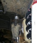
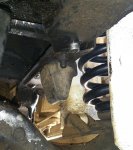
Weird frame rivet?

Disclaimer: Links on this page pointing to Amazon, eBay and other sites may include affiliate code. If you click them and make a purchase, we may earn a small commission.

blueovalboy69302

New member
Joined
May 1, 2017
Messages
2
Reaction score
0
Hello,

I am having an alignment problem with my '81 bronco.  When I would turn the wheel left and right the drivers side frame rail at the steering gear would move left and right. I realized there was a weird rivet / bolt holding the engine cross member in place.  It does not look factory.  This is where the frame is moving in and out (left and right).  I am thinking about cutting it off and installing a bolt but I'm not sure I can get a bolt in this location.  Just trying to figure out my next course of action! Pictures attached.

Thank you,

Phil
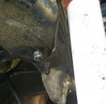
Rivet1.jpg

Rivet2.jpg

Rivet3.jpg


miesk5

96 Bronco 5.0
Staff member
Moderator
Joined
Oct 18, 2005
Messages
9,071
Reaction score
1,019
Location
Floating in the Pacific
Yo Phil,

Welcome!

I believe this will help:

Steering Box Frame Crack Repair 
Source: by Ford

steeringcrack.jpg

The following areas of the frame should be checked before performing a steering gear frame liner repair: the frame rail near the steering gear top and bottom flanges, and the frame rail at the steering gear bolt heads. If there are cracks in these areas of the frame, the frame must be replaced. Inspect the mounting surface of the steering gear for signs of motion, loose rivets or cracks. Removal of the steering gear may be necessary to check for cracks in the frame liner. If the frame liner is cracked or has loose rivets, repair the liner by using Frame Repair Kit E6TZ-5K130-A. If necessary a steering gear liner to frame, rivet repair can be made by using the procedures described in the illustration.

Rivet Removal and Replacement
1. Drill a 1/8-inch hole through rivet.
2. Redrill the hole through the shank of the rivet with an 11/32-inch drill.
3. Use an air chisel to remove rivet head.
4. Drive out rivet with a punch or other suitable tool.
5. Line drill one 7/16-inch hole marked "V" to 9/16-inch diameter.
6. Install one 9/16-inch bolt in the direction shown in the first illustration.
7. Position bolt head on top (next to crossmember) with hex head flat to the rear to provide best clamping.
8. Install one 9/16-inch washer nut side only and one 9/16-inch nut. Tighten to 190 N-m (140 ft-lb).
NOTE: Tack weld the nut to the bolt as shown in the second illustration.

...

Rivet Replacement with Bolts

For other TSBs, check here.
TSB 97-4-7 FRAME - RIVET REPLACEMENT WITH BOLTS
Publication Date: FEBRUARY 17, 1997 
LIGHT TRUCK:
1980-1996 BRONCO 
1980-1997 ECONOLINE, F-150-350 SERIES 
1983-1997 RANGER 
1984-1990 BRONCO II 
1986-1997 AEROSTAR 
1988-1997 F SUPER DUTY, F-47 
1991-1997 EXPLORER 
rivetreplacement.jpg
ISSUE: Damaged or loose frame rivets should be replaced with approved service bolts. WELDING IS NOT ACCEPTABLE. 

ACTION: If service is required, replace standard rivets with approved service bolts. Refer to the following Service Procedure for details.

NOTE: THE "HUCK" RIVET BETWEEN THE #1 CROSSMEMBER AND THE LH FRAME RAIL SHOULD BE SERVICED PER TSB 91-25-18. THIS PROCEDURE DOES NOT APPLY.

SERVICE PROCEDURE 
Inspect for a loose or damaged rivet. 
Remove any damaged or loose rivets. 
1.) Drill a 3.175mm (1/8") hole through the rivet. 
2.) Redrill the same hole through the shank of the rivet. 
3.) Use an 8.731mm (11/32") drill for 3/8" and 10mm rivets. 
4.) Use a 9.525mm (3/8") drill for 11.113mm (7/16") rivets. 
5.) Remove the rivet head with an air chisel. 
6.) Drive out the rivet with a punch and hammer. 
7.) Line ream the hole to the replacement bolt nominal size with a hole tolerance of 0.127mm (0.005"). 
8.) Free hole of burrs after reaming to allow bolt head and nut to seat properly. 
9.) Select the bolt length to have a minimum of two (2) threads protruding from outer face of nut. Refer to the Bolt Selection Chart for correct parts usage.

NOTE: IF A ****** HEAD NUT AND BOLT ARE NOT AVAILABLE, GRADE 5 HEX HEADS MAY BE SUBSTITUTED WITH ONE (1) FLATWASHER REQUIRED UNDER THE NUT AND ONE (1) FLATWASHER REQUIRED UNDER THE BOLT HEAD.
NOTE: GRADE 8 BOLTS MAY BE SUBSTITUTED FOR ANY APPLICATION.

Check to be sure there is a 12.7mm (1/2") minimum clearance of bolt to adjacent components, except engine and transmission, which must have at least 19.05mm (3/4") clearance to allow for powertrain roll.

10.) Tighten the bolts to the specifications shown in the Bolt Selection Chart.

...

Frame Service - Drilling Precautions 

CAUTION: Do not drill holes in the frame flanges. This will reduce the strength of frame (5005). 

If a hole must be drilled in the frame, make sure that it meets all of the following requirements: 
1. The hole is located in the upper half of the frame. 
2. The edge of the drilled hole and the edge of the nearest hole are at least 25mm (1 inch) apart. 
3. The edge of the drilled hole is at least 25mm (1 inch) from the edge of the ******. 
4. The drilled hole is not adjacent to any other existing brackets or components of frame. 

Welding Precautions 

CAUTION: Disconnect the battery ground cable (14301) before using any electric welding equipment. 

All welding on frame must be done with electric welding equipment, and the heat should be kept in a small area to prevent change in hardness of the metal. Do not use gas welding equipment. A double reinforcement must be added to frames where heat or weld is applied to the area to be repaired. The welds are to run lengthwise along the reinforcement when a reinforcement is to be welded to the frame side rail. 

Frame Strength Identification 
F-Series, F-Super Duty Chassis Cab and Bronco all use a 36,000 psi steel frame. 

Frame Straightening 
Misalignment of frame can be corrected by straightening the out-of-line parts or by replacing the crossmembers, braces, or brackets if they are badly damaged. 

WARNING: DO NOT STRAIGHTEN FRONT FRAME RAIL CONVOLUTES. 
Straightening should be attempted on frames that fail to meet specifications of the diagonal checking method or where damage is visually apparent. 

However, to prevent internal stresses in the metal, frame straightening should be limited to parts that are not severely bent. If heat is needed to straighten a frame member, keep the temperature below 649�C (1200�F) (a dull red glow). Excessive heat may weaken the metal in the frame members and cause permanent damage. 

Frame Reinforcing 

After a bent frame member has been straightened, inspect the member closely for cracks. If any cracks show, the frame member should be reinforced or replaced. 

Reinforcements should be made from angle or flat stock of the same material and thickness as the frame member being reinforced, and should extend a minimum of 152.40mm (6 inches) to either side of the crack. Ideally, the reinforcement should be cut from the corresponding area of a similar frame. 

Weld Attachment 

To ensure a quality repair, adhere to the following procedure if it is necessary to weld reinforcements to the frame. 
1. Wire brush the area around the crack to remove the paint, grease, mud, etc., and to expose the crack completely and ensure good weld adhesion. 
2. To stop the crack from spreading, drill a 6.35mm (1/4-inch) hole at a point 12mm (0.50 inch) beyond the root of the crack. 
3. Grind out the full length of the crack to the hole to form a V-shaped slot with the base of the V-slot contacting the reinforcement. 
4. The base of the V-slot should have at least a 1.52mm (0.06-inch) opening to ensure weld penetration to the reinforcement when welding the crack. 
5. Drill clearance holes in the reinforcements to clear rivet heads and bolt heads or nuts where necessary. 
6. In the event that repair is required on more than one frame surface (i.e., a ****** crack that extends into the web), two pieces of flat stock (one for each surface) should be utilized and welded together where they join. The web reinforcement should be a minimum of 76.20mm (3.0 inches) high and have a 63.50mm (2.5-inch) radius at each of the two corners. 
7. Completely clean the surface of frame under and around the reinforcements. 
8. Clamp the reinforcements securely to the frame prior to welding. 
9. Weld the reinforcement all around after welding the crack V-slot. 
10. The ****** edge weld should be ground smooth after all pit holes have been filled by the weld. 
11. If a damaged bolted-on frame bracket is to be replaced, the new bolts, washers, and nuts should be of the same specifications and bolt torques as the original parts. 
12. In cases where it is necessary to remove rivets, replace them with Property Class 9.8 metric (Grade 8 ) nuts, bolts and washers of the next larger size (i.e., for 3/8-inch diameter rivets use 7/16-inch bolts, for 7/16-inch diameter rivets use 1/2-inch bolts). This requires line drilling of the holes to the same diameter as the new bolt (i.e., either 0.437 diameter or 0.500 diameter). 

Frame Member Replacement 

If a damaged frame member is to be replaced, new bolts, Property Class 9.8 metric (Grade 8 ) fasteners and rivets required for replacement of parts should be of the same specifications as the original bolts or rivets. In cases where it is necessary to substitute a bolt for a rivet, use the next larger size bolt.

 
Last edited by a moderator:
OP
OP
B

blueovalboy69302

New member
Joined
May 1, 2017
Messages
2
Reaction score
0
Thank you! So I ground off the bottom of the "rivet". Then there as a pin exposed inside a big sleeve. The pin was just over 5/16th in diameter. And I used a punch to drive it out. The bigger piece that goes through the frame appears to be about 11/16ths. I'm going to put a flapper wheel on the grinder and see if the 11/16ths is a shoulder measurement or if someone drilled the frame this large.


Members online

No members online now.

Latest posts

Forum statistics

Threads
22,520
Messages
135,982
Members
25,125
Latest member
ReturnToHangar
Top