wheel problem

Disclaimer: Links on this page pointing to Amazon, eBay and other sites may include affiliate code. If you click them and make a purchase, we may earn a small commission.

Devil Dog08

New member
Joined
Nov 27, 2008
Messages
184
Reaction score
4
Location
philadelphia pa
hey yall hope everyones doing well........well it seems to be one problem after another on my 1995 full size 5.8 bronco with 184000 miles and after that egr problem that baffeld me for weeks im ready to put a cover on my truck and give it to my kids when i pass away and let them enjoy all the DIYs that i did on it. OK so here is my new issue  when I am taking off from a dead stop I hearing  a sound like I'm driving on a washboard with a little grinding. but the truck is not riding like I'm on a washboard the sound only lasts for a few seconds and is coming from either the front left  wheel or the left rear wheel. its really hard to determine which wheel it is. so anyway I'm leaning toward a wheel bearing  . I jacked up the left front end  spun the wheel didn't hear no noise I tried to shake it side to side   and from top to bottom looking for signs of a bad wheel bearing. there was no shaking everything was tight  so now I'm wondering  because I put warn manual hubs on the truck  a few years ago wouldn't all the pieces that are  inside the hub for the locking hubs prevent the wheel from shaking even if the wheel bearing is bad compared to  a vehicle without 4 wheel drive?  sorry this was so long but I'm trying to give every detail .thanks mike

.


Bully Bob

TOP GUN
Moderator
Joined
May 23, 2004
Messages
3,844
Reaction score
12
Location
Boulder City, Nevada (Las Vegas area)
IMHO  NO.., the wheel bearings (inside the hub) rest/spin on spindle. Therefore, a"bad" bearing could be

felt by wiggling the tire/wheel but, not necessarily. 

RU sure the hubs are "unlocking" completely/correctly..?

A bad wheel bearing can damage the spindle.


miesk5

96 Bronco 5.0
Staff member
Moderator
Joined
Oct 18, 2005
Messages
9,071
Reaction score
1,019
Location
Floating in the Pacific
Yo Dogg,

As Bob suggested;

"...Manual locking hubs diagnosis. Place the transfer case in 2-wheel drive and raise the front wheels off the ground.

miesk5 note, CHOCK BOTH REAR WHEELS. USE JACK STANDS:

Jack, Floor, F-150, F-250 (4x4 Only) and Bronco

To raise front wheel, place jack in position from front of vehicle under axle.

http://www.diesel-dave.com/vehic/manual/stj/images/y5228a.gif

...

When in the unlocked position, the wheels should be able to turn freely. Then lock each of the front hubs and rotate the front wheels. The additional load of the drivetrain components should be felt once the hub has been engaged. In addition, the axle and front driveshaft should be moving along with the wheel. Disengage the hubs and repeat the procedure to check that the hubs have smoothly disengaged..."

by Ford


miesk5

96 Bronco 5.0
Staff member
Moderator
Joined
Oct 18, 2005
Messages
9,071
Reaction score
1,019
Location
Floating in the Pacific
Yo,

I over wrote this;

"...Bearing rumble sounds like marbles being tumbled. This condition is usually caused by a malfunctioning wheel bearing. The lower pitch is the result of wheel bearings turning at only about one-third of driveshaft speed. Wheel bearing noise also may be high-pitched, similar to gear noise, but will be evident in all four driving modes..." by Ford

Any chance a helper can safely walk next to left side front and later left side rear wheels and listen for that noise using a mechanic's stethoscope, available @ Harbor Freight for about $5.00 or using short garden hose section?

 
OP
OP
Devil Dog08

Devil Dog08

New member
Joined
Nov 27, 2008
Messages
184
Reaction score
4
Location
philadelphia pa
thanks like always........ so  today i lifted the truck  and tested the locking hubs both side working fine  . didn't see top guns post so i took the locking hub assembly out took a look at the bearings had the rotor off the bearings were  fine  repacked them put it all back together.  i then put the rear of the truck on jackstands and i noticed both rear wheels are sliding in and out less then a quarter  of an inch..with the truck running i put it in drive  i couldn't distinguish  if i was hearing the drum spinning or the rear was making some kind of noise I'm sure when the truck is raised off the ground  and power is put  to the wheels it sounds different............


miesk5

96 Bronco 5.0
Staff member
Moderator
Joined
Oct 18, 2005
Messages
9,071
Reaction score
1,019
Location
Floating in the Pacific
Yo Dogg,

OK.

Look @

96 Bronco-F-Series Workshop Manual (PARTIAL) by FORD via

http://www.diesel-dave.com/vehic/manual/stj/stjleft.htm

96 is same as most earlier years especially 92-96, except for:

92 through 95 uses the Electronic Engine Control, version Four (EEC-IV, aka On Board Diagnostics (OBD-I)) engine management computer

96 uses the OBD-II (EEC-V) engine management computer;

4WABS (93-96);

RABS (87-92);

Air Bag (94-96);

3 ***** Automatic Locking Hubs (Built from May 95 through 96); Spark Plug Wire Routing & Firing Order (The firing order for 1987-1993 5.0Ls is 1-5-4-2-6-3-7-8. The firing order for 1994- 96 5.0Ls & all 5.8Ls is 1-3-7-2-6-5-4-8.);

R134a in 94-96;

2-piece Spindle Rolling Diaphragm Seal (RDS) used on 5/95 to 96 Broncos & F Series 1/2-ton 4WD;

Mass Air Flow in 95 5.8 California models and in all 96s, other years used Manifold Absolute Pressure Sensor (MAP).

96 5.8 do not have the Air Injection (AIR), Secondary Air Injection; Pump (Smog Pump), Thermactor Air Bypass (TAB) & Thermactor Air Diverter (TAD) Solenoids; Diverter, Check & Bypass Valves, Cross-Over Tube, etc. But 96 5.0 does have the system.

The 96, Vapor Management Valve (VMV) replaces the canister purge valve (CanP valve) used in EEC IV.

The Speed Control Deactivation Switch (SCDS) in a 93 Bronco is located on the driver side frame rail, but in 94 through 96 it is on the master cylinder.

Still researching other differences.

Go to Section 05-00: Axle and Driveshaft, Service

DIAGNOSIS AND TESTING

Inspection and Verification

Non-Axle Noise

nspection and Verification

Certain rear axle (4001) and driveline trouble symptoms are also common to the engine (6007), transmission (7003), rear wheel bearings (1225), tires and other parts of the vehicle. For this reason, make sure the cause of the trouble is in the rear axle before adjusting, repairing or replacing any of its parts. Refer to Diagnosis and Testing in Section 00-04.

Certain trouble symptoms may be caused by limited slip differentials. Check the vehicle certification and axle ratio tag to determine the type of differential.

U-Joint Inspection

Prior to checking driveline angularity, inspect the universal joints for proper operation.

Place the vehicle on a frame hoist and rotate the driveshaft (4602) by hand. Check for rough operation or seized universal joints. If the universal joint shows signs of seizure, excessive wear or improper seating, scribe alignment marks on the driveshaft and rear axle companion ******. Remove the driveshaft and remove and replace the universal joint. Install the driveshaft in the marked original position.

*** Skipping to **** ;

There are a few other conditions that can sound like axle noise and have to be considered in diagnosis.

The three most common are exhaust, tires and trim mouldings. Make sure that none of the following are the cause of the noise before proceeding with an axle teardown and diagnosis.

In certain conditions, the pitch of the exhaust may sound like gear whine. At other times, it can be mistaken for wheel bearing rumble.

Tires — especially snow tires — can have a high-pitched tread whine or roar similar to gear noise. Radial tires, to some degree, have this characteristic. Any non-standard tire with an unusual tread construction may also emit a roar or whine-type noise.

Trim, grille and mouldings can also cause whistling or whining noises.

Analysis of Gear Noise

Gear Howl and Whine

Before disassembling the axle to diagnose and correct gear noise, eliminate the tires, exhaust, trim items, roof racks, axle shafts and rear wheel bearings as possible causes.

The noises listed on the Road Test Form in this section usually have specific causes that can be diagnosed by observation as the unit is disassembled. The initial clues are, of course, the type of noise heard on the road test and the driving conditions.

Bearing malfunctions will normally be obvious at disassembly. As noted earlier, inner and outer pinion bearings make a high-pitched, whistling noise, usually at all speeds. If there is only one pinion bearing that is malfunctioning, the noise may vary in different driving phases.

Pinion bearings are frequently replaced unnecessarily on axles with low mileage under 24,139 km (15,000 miles) when correcting gear noise. They should not be replaced unless they are actually scored or damaged, or there is a specific differential pinion bearing noise. Examine the large end of the rollers for wear. If the pinion bearing's original blend radius has worn to a sharp edge, the pinion bearing should be replaced.

Remember that the low-pitched rumble of a malfunctioning wheel bearing can also be caused by the exterior luggage rack or tires.

Rear wheel bearing noise might be mistaken for pinion bearing noise. Inspect the rear wheel bearing carefully before tearing down the axle.

Etc.

...

*** Skipping to ****

Section 05-02G: Axle, Integral Carrier, 8.8-Inch Ring Gear

SPECIFICATIONS

Axle Shaft End Play

Axle shaft end play is allowable up to 0.762mm (0.030 inch), but can be as low as 0.127mm (0.005 inch). It is controlled by the u-washer (4N237) that holds the axle shaft (4234) in the pocket of the differential side gear (4236). To reduce clearance, replace differential side gears, Traction-Lok® clutch plates if equipped, differential side gear ****** washers (4228) or axle shafts as required.

 
W

Wheel problem

Guest
So I have a 1996 ford bronco with a 351 5.8l motor, but anyway the problem is that my right front wheel is locked up and I have done 4-5 wheel bearing replacements on it before I had let it sit for 7 years , but Im trying to get the truck road ready and can't figure out the problem of what keeps throwing the wheel bearing


miesk5

96 Bronco 5.0
Staff member
Moderator
Joined
Oct 18, 2005
Messages
9,071
Reaction score
1,019
Location
Floating in the Pacific
Yo Guest,

WELCOME!

For now;


Section 04-00: Suspension, Service


1996 F-150, F-250, F-350, F-Super Duty and Bronco Workshop Manual

ADJUSTMENTS

Wheel Bearings, Front


  1. Raise the vehicle until the tire clears the floor.
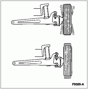
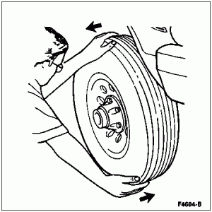
  1. Grasp each front tire at the top and bottom and push the wheel (1007) inward and outward while lifting the weight of the tire off the front wheel bearings.

    f4604b.gif
     
  1. Make sure the wheel rotates freely and the brake pads are retracted sufficiently to allow movement of the wheel assembly.
  1. If the wheel/hub-rotor is loose on the front wheel spindle (3105) or does not rotate freely, adjust the front wheel bearings as described in the appropriate section in Group 04.
  2. Check that the final end play of the front disc brake hub and rotor on the front wheel spindle is 0.00-0.50mm (0.000-0.002 inch).
  3. ani_caut.gif CAUTION: Excessive end play or torque greater than 2.3 Nm (20 lb-in) to rotate hub and rotor will result in excessive wear of wheel bearings.


G2 INSPECT WHEEL BEARINGS


  • Spin front tires by hand to check for wheel bearing roughness. Check bearing end play.
Is end play OK?
f9355a.gif


Section 05-03C: Wheel Hubs and Bearings, Front Wheels, 4-Wheel Drive


1996 F-150, F-250, F-350, and Bronco Workshop Manual

ADJUSTMENTS

Front Wheel Bearing, Automatic Locking Hubs


SPECIAL SERVICE TOOL(S) REQUIRED


Description


Tool Number


Hub Nut Wrench


T95T-1197-A


Hub Nut Wrench


T95T-1197-B


  1. Raise the vehicle and install safety stands.
  1. Remove the hublock assembly. Refer to Automatic Locking Hub removal and installation in this section.
  1. Remove retaining lock ring or C-ring and three-piece ****** washers. Remove cam assembly and wheel nut retaining key (if not already removed).
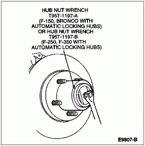
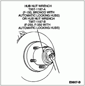
  1. Loosen wheel bearing retainer (nut) using Hub Nut Wrench T95T-1197-A for F-150 and Bronco or T95T-1197-B for F-250 and F-350 with automatic locking hubs. While rotating rotor and hub, retighten wheel bearing retainer (nut) to 68 Nm (50 lb-ft) to seat wheel bearings.

    e9807b.gif
     
  1. Back off nut 90 degrees (1/4 turn). Tighten wheel retainer nut to 1.8 Nm (16 lb-in). If necessary, tighten nut to next slot to allow installation of retainer key.
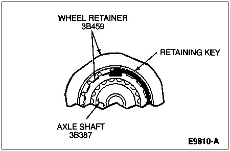
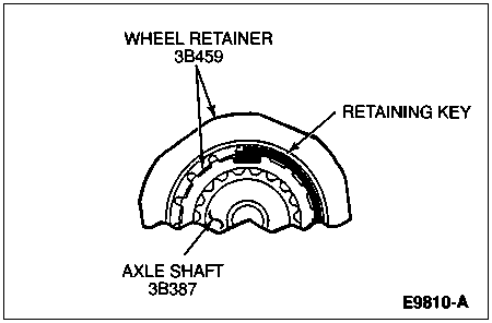
  1. Install retaining key into the spindle keyway by inserting the short leg into the aligned slot in nut. Press all the way into position until curved portion of retaining key is seated into counterbore of wheel retainer (nut).

    e9810a.gif
     
  1. Install cam assembly.
  1. ani_caut.gif CAUTION: Improper sequence of three-piece ****** washers will result in excessive wear of assembly.

    Install three washers in order: metal washer first, plastic washer second and splined washer last.
  1. Install C-ring or lock ring. Align legs of cam assembly for installation of hub body.
  1. Check that the final end play of the front disc brake hub and rotor on the front wheel spindle is 0.00-0.50mm (0.000-0.002 inch).
  1. ani_caut.gif➡️➡️ CAUTION: Excessive end play or torque greater than 2.3 Nm (20 lb-in) to rotate hub and rotor will result in excessive wear of wheel bearings.

    Torque required to rotate the front disc brake hub and rotor is not to exceed 2.3 Nm (20 lb-in).
  1. Install hublock. Tighten screws to 4-6 Nm (35-53 lb-in).
  1. Remove safety stands. Lower vehicle.
 
Manual Locking Hubs


SPECIAL SERVICE TOOL(S) REQUIRED


Description


Tool Number


Hub Locknut Wrench


T83T-1197-B


  1. Raise the vehicle and install safety stands. Remove caliper and brake pads. Refer to Section 06-03.
  1. Remove the hublock assembly. Refer to the Manual Locking Hub removal and installation procedures in this section.
  1. Remove C-ring and three-piece ****** washers (if not already removed).
  1. Remove the outer lock nut with Hub Lock Nut Wrench T83T-1197-B for F-150 and Bronco or Spanner Locknut Wrench D85T-1197-A or equivalent for F-250 and F-350. Remove the lockwasher and loosen inner lock nut.
  1. Using spanner lock nut wrench while rotating the front disc brake hub and rotor (1102) back and forth, tighten the inner lock nut to 68 Nm (50 lb-ft) to seat the bearing.
  1. Back off the lock nut 90 degrees.
  1. NOTE: Hole pattern of lockwasher is offset with keyway to provide half-position settings by flipping washer over to obtain closest hole.

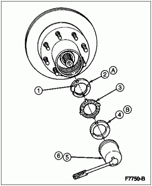
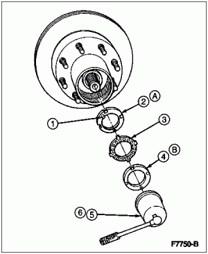
    Install the lockwasher so the key is positioned in the groove of the front wheel spindle (3105). Tighten the inner lock nut, aligning the pin into the nearest lockwasher hole.

    f7750b.gif


    Item


    Part Number


    Description


    1


    Pin (Part of 1195)


    2


    1195


    Inner Lock Nut


    3


    1198


    Lockwasher


    4


    1197


    Outer Lock Nut


    5


    T83T-1197-B
    (Model 44)


    Hub Lock Nut Wrench


    6


    D85T-1197-A (Models 50 and 60)


    Spanner Locknut Wrench


    A


    Tighten to 68 Nm (50 Lb-Ft). Back Off 90 Degrees.


    B


    Tighten to 217-278 Nm (160-205 Lb-Ft)

  1. Install the outer lock nut and tighten to 217-278 Nm (160-205 lb-ft) using Hub Locknut Wrench T83T-1197-B for F-150 and Bronco or Spanner Locknut Wrench D85T-1197-A or equivalent for F-250 and F-350.
  1. Check the final end play of the front wheel spindle. It should be 0.00-0.05mm (0.000-0.002 inch).
  1. Torque required to rotate the front disc brake hub and rotor is not to exceed 2.3 Nm (20 lb-in).
  1. ani_caut.gif ➡️➡️CAUTION: Improper sequence of three-piece ****** washers will result in excessive wear of assembly.

    Install three washers in order: metal washer first, plastic washer second and splined metal washer third. Install C-ring.
  1. Install the hublocks. Refer to Locking Hubs in the Removal and Installation portion of this section.
  1. Remove the safety stands. Lower the vehicle.

Section 05-03C: Wheel Hubs and Bearings, Front Wheels, 4-Wheel Drive


1996 F-150, F-250, F-350, and Bronco Workshop Manual

ADJUSTMENTS

Front Wheel Bearing


Automatic Locking Hubs


SPECIAL SERVICE TOOL(S) REQUIRED


Description


Tool Number


Hub Nut Wrench


T95T-1197-A


Hub Nut Wrench


T95T-1197-B


  1. Raise the vehicle and install safety stands.
  1. Remove the hublock assembly. Refer to Automatic Locking Hub removal and installation in this section.
  1. Remove retaining lock ring or C-ring and three-piece ****** washers. Remove cam assembly and wheel nut retaining key (if not already removed).
  1. Loosen wheel bearing retainer (nut) using Hub Nut Wrench T95T-1197-A for F-150 and Bronco or T95T-1197-B for F-250 and F-350 with automatic locking hubs. While rotating rotor and hub, retighten wheel bearing retainer (nut) to 68 Nm (50 lb-ft) to seat wheel bearings.

    e9807b.gif
     
  1. Back off nut 90 degrees (1/4 turn). Tighten wheel retainer nut to 1.8 Nm (16 lb-in). If necessary, tighten nut to next slot to allow installation of retainer key.
  1. Install retaining key into the spindle keyway by inserting the short leg into the aligned slot in nut. Press all the way into position until curved portion of retaining key is seated into counterbore of wheel retainer (nut).

    e9810a.gif
     
  1. Install cam assembly.
  1. ani_caut.gif CAUTION: Improper sequence of three-piece ****** washers will result in excessive wear of assembly.

    Install three washers in order: metal washer first, plastic washer second and splined washer last.
  1. Install C-ring or lock ring. Align legs of cam assembly for installation of hub body.
  1. Check that the final end play of the front disc brake hub and rotor on the front wheel spindle is 0.00-0.50mm (0.000-0.002 inch).
  1. ani_caut.gif ➡️➡️CAUTION: Excessive end play or torque greater than 2.3 Nm (20 lb-in) to rotate hub and rotor will result in excessive wear of wheel bearings.

    Torque required to rotate the front disc brake hub and rotor is not to exceed 2.3 Nm (20 lb-in).
  1. Install hublock. Tighten screws to 4-6 Nm (35-53 lb-in).
  1. Remove safety stands. Lower vehicle.
 
Manual Locking Hubs


SPECIAL SERVICE TOOL(S) REQUIRED


Description


Tool Number


Hub Locknut Wrench


T83T-1197-B


  1. Raise the vehicle and install safety stands. Remove caliper and brake pads. Refer to Section 06-03.
  1. Remove the hublock assembly. Refer to the Manual Locking Hub removal and installation procedures in this section.
  1. Remove C-ring and three-piece ****** washers (if not already removed).
  1. Remove the outer lock nut with Hub Lock Nut Wrench T83T-1197-B for F-150 and Bronco or Spanner Locknut Wrench D85T-1197-A or equivalent for F-250 and F-350. Remove the lockwasher and loosen inner lock nut.
  1. Using spanner lock nut wrench while rotating the front disc brake hub and rotor (1102) back and forth, tighten the inner lock nut to 68 Nm (50 lb-ft) to seat the bearing.
  1. Back off the lock nut 90 degrees.
  1. NOTE: Hole pattern of lockwasher is offset with keyway to provide half-position settings by flipping washer over to obtain closest hole.

    Install the lockwasher so the key is positioned in the groove of the front wheel spindle (3105). Tighten the inner lock nut, aligning the pin into the nearest lockwasher hole.

    f7750b.gif


    Item


    Part Number


    Description


    1


    Pin (Part of 1195)


    2


    1195


    Inner Lock Nut


    3


    1198


    Lockwasher


    4


    1197


    Outer Lock Nut


    5


    T83T-1197-B
    (Model 44)


    Hub Lock Nut Wrench


    6


    D85T-1197-A (Models 50 and 60)


    Spanner Locknut Wrench


    A


    Tighten to 68 Nm (50 Lb-Ft). Back Off 90 Degrees.


    B


    Tighten to 217-278 Nm (160-205 Lb-Ft)

  1. Install the outer lock nut and tighten to 217-278 Nm (160-205 lb-ft) using Hub Locknut Wrench T83T-1197-B for F-150 and Bronco or Spanner Locknut Wrench D85T-1197-A or equivalent for F-250 and F-350.
  1. Check the final end play of the front wheel spindle. It should be 0.00-0.05mm (0.000-0.002 inch).
  1. Torque required to rotate the front disc brake hub and rotor is not to exceed 2.3 Nm (20 lb-in).
  1. ani_caut.gif ➡️➡️CAUTION: Improper sequence of three-piece ****** washers will result in excessive wear of assembly.

    Install three washers in order: metal washer first, plastic washer second and splined metal washer third. Install C-ring.
  1. Install the hublocks. Refer to Locking Hubs in the Removal and Installation portion of this section.
  1. Remove the safety stands. Lower the vehicle.


Staff online

Members online

Latest posts

Forum statistics

Threads
22,516
Messages
135,940
Members
25,117
Latest member
danno
Top