1989 Bronco 8cyl XLT Idles bad and low power and cuts off during down

Disclaimer: Links on this page pointing to Amazon, eBay and other sites may include affiliate code. If you click them and make a purchase, we may earn a small commission.

Ymehawa11

New member
Joined
Nov 20, 2016
Messages
13
Reaction score
0
I have a 1989 Bronco XLT 8Cyl 5.0 has a rebuilt motor, transmission, Hego, the sensor on the side of the alternator, new dist and a long list of other parts over this last year. I just swapped out the fuel filter and in line Fuel pump di not swap out low pressure pump in tank, and now it losses power during down shift and has 30% or so less power when driving. 

Codes

Engine Off

11

Engine on

41 Hego Sensor

77 Operator Error During Dynamic Fault

The new gas pump is

Master Pro

  • Fuel Pump
  • In-Line
  • Flow Rate (gph): 25 gph
Going nuts, Help


miesk5

96 Bronco 5.0
Staff member
Moderator
Joined
Oct 18, 2005
Messages
9,071
Reaction score
1,019
Location
Floating in the Pacific
Yo Ymehawa11,

Welcome!

Did the symptoms occur before you replaced those parts or after?

code

Contaminated Oxygen Sensor pics w/Diagnosis, General

Source: by Tomco

Contamination will make the sensor function inaccurately, which will lead to poor performance, poor fuel economy and high emissions. @ http://redirect.viglink.com/?format=go&jsonp=vglnk_147974637430615&key=6ed47b392b9edfe394b9e89b72717104&libId=ivsaovt601000bgv000MA7ipqx9k2&loc=http%3A%2F%2Fwww.fullsizebronco.com%2Fforum%2F7-1980-96-bronco-tech%2F155932-302-iac-signal-2.html&v=1&out=http%3A%2F%2Fcds.activant.com%2FC2C%2FC01%2F68%2F541%2F824663110.pdf&ref=http%3A%2F%2Fwww.fullsizebronco.com%2Fforum%2F6135985-post5.html&title=302%20IAC%20Signal%3F%3F%20-%20Page%202%20-%20Ford%20Bronco%20Forum&txt=Contaminated%20Oxygen%20Sensor%20pics%20w%2FDiagnosis%2C%20General%20%0ASource%3A%20by%20Tomco%0AContamination%20will%20make%20the%20sensor%20function%20inaccurate...

DTC 41, 42, 91, 92, 136, 137,139, 144, 171, 172, 173, 175, 176, 177 & some Possible Causes for Rich & Lean HEGO The engine temperature must be greater than 50°F (10°C) to pass the KOEO Self-Test and greater than 180°F (82°C) to pass the KOER Self-Test. To accomplish this, the engine should be at normal operating temperature

Source: by Ryan M (Fireguy50)

DTC 41, 42, 85 OR THREE DIGIT CODES 171, 172, 173, 179, 181, 182, 183 & 565 are received , Check for proper HEGO Ground; in Catalytic Converter Diagnosis TSB 91-12-11 for 86-91 Bronco, F Series, & Econoline

Source: by Ford

Publication Date: JUNE 12, 1991

TRUCK: 1986-91 BRONCO, ECONOLINE, F-150-350 SERIES

1988-91 F SUPER DUTY, F47

ISSUE: Lack of power or a no start condition may be diagnosed as an exhaust restriction caused by a plugged catalytic converter. A plugged catalytic converter (internal deterioration) is usually caused by abnormal engine operation.

ACTION: Diagnose the catalytic converter to confirm internal failure. Refer to the Catalyst and Exhaust System Diagnostic Section, in the Engine/Emissions Diagnostic Shop Manual and the following procedures for service details.

SERVICE PROCEDURE

1. Lack of proper HEGO operation may cause, or be the result of a rich or lean fuel condition, which could cause additional heat in the catalyst. Perform self test KOEO and KOER, service any codes.

NOTE: IF TWO DIGIT CODES 41, 42, 85 OR THREE DIGIT CODES 171, 172, 173, 179, 181, 182, 183 AND 565 ARE RECIEVED, CHECK FOR PROPER HEGO GROUND.

Here is the wiring diagram for the HEGO.

It shows that the heater circuit is not used on 5.0 engines.

http://www.revbase.com/BBBMotor/Wd/DownloadPdf?id=21138

Just in case check that G802 Shown in diagram is good on RH inner fender behind headlights;

If the HEGO ground is good, the following areas may be at fault:

* Ignition Coil

* Distributor Cap

* Distributor Rotor

* Fouled Spark Plug

* Spark Plug Wires

* Air Filter

* Stuck Open Injector

* Fuel Contamination with Engine OIL

* Manifold Leaks Intake/Exhaust

* Fuel Pressure

* Poor Power Ground

* Engine Not At Normal Operating Temperature

* HEGO Sensor

2. Spark timing that is ******** from specification may increase exhaust gas temperature and shorten catalyst life. Refer to the following procedure for service details.

a. Check spark timing. Check base timing with spout disconnected. Set base timing to the specification on the vehicle emission decal.

b. Check computed timing. How to Set the timing on an EFI Ford spout connected. by Ryan M. @ http://www.fuelinjectedford.com/page71.html

NOTE: COMPUTED TIMING IS EQUAL TO BASE TIMING PLUS 20° BTDC ± 3°.

3. Misfiring spark plugs may cause an unburned fuel air mixture to pass through the catalyst, which could cause higher than normal catalyst temperatures. Refer to the following procedure for service details. Check secondary ignition, hook the vehicle up to an engine analyzer and check for a secondary ignition misfire.

Spark Plug Diagnosis @ http://www.aa1car.com/library/reading_spark_plugs.jpg

NOTE: SERVICE ANY ITEM THAT IS NOT PERFORMING AT PROPER SPECIFICATIONS BEFORE CONTINUING.

4. Fuel pressure that is too high may cause rich air fuel mixtures to pass through the catalyst which could cause higher than normal catalyst temperatures. Refer to the following procedure for service details.

a. Check fuel pressure, install fuel pressure gauge, start and run the engine at idle. Fuel pressures between 28 and 34 PSI are typical (4.9L typically is 15 PSI higher).

b. Disconnect the vacuum line going to the fuel pressure regulator. Fuel pressure typically jumps to 40 PSI ± 3 PSI (4.9L typically is 15 PSI higher). Visually inspect vacuum line for raw fuel.

NOTE: FUEL PRESSURES ABOVE THESE VALUES SHOULD BE CORRECTED. HOWEVER, THIS MAY NOT BE THE CAUSE OF THE CONCERN. SERVICE AS NECESSARY.

5. Throttle plates in the throttle body not returning to the proper closed position may cause excessive catalyst temperatures during downhill grades. Refer to the following procedure for service details. Visually inspect the throttle body and linkage for:

* Binding or sticking throttle linkage.

* Tight speed control linkage or cable.

* Vacuum line interference.

* Electrical harness interference.

NOTE: AFTERMARKET GOVERNORS, THROTTLE LINKAGE AND CABLES ASSOCIATED WITH POWER TAKE-OFF UNITS, MAY ALSO INTERFERE WITH PROPER THROTTLE RETURN. SERVICE AS NECESSARY.

6. It is extremely important that all systems related to the engine and emission systems operate properly.

a. Visually inspect the engine compartment to make sure all vacuum hoses and spark plug wires are properly routed and securely connected.

b. Inspect all wiring harnesses and connectors for insulation damage, burned, overheated, loose or broken conditions.

c. Verify proper operation of the thermactor system. Thermactor systems that fail to dump thermactor air to the atmosphere properly or at the correct time can cause high catalyst temperatures.

d. Visually inspect thermactor system for damaged or kinked hoses and perform a function test on following components: air control valve, check valve, silencer, filter and the air bypass solenoid.

e. Verify proper operation of the engine cooling system thermostat.

...

See my Vacuum leak diagnosis in post #20 @ http://broncozone.com/topic/23994-90-58l-getting-continuous-code-33-and-running-code-44/?p=125535

There is a way to test for fuel volume, but it is dangerous.

Is it a C6 transmission?

 
Last edited by a moderator:

miesk5

96 Bronco 5.0
Staff member
Moderator
Joined
Oct 18, 2005
Messages
9,071
Reaction score
1,019
Location
Floating in the Pacific
Yo,

this TSB is for later years, but worth a look;

DTC 172, 173 or 41, Common Locations for Short Circuits TSB 95-02-11 on 94-95 Bronco & Trucks

Source: by Ford

Scroll dn to last;

http://www.supermotors.net/registry/media/646262

87-89; Fuel Injected Engines - "...Two electric pumps are used on fuel injected models; a low pressure boost pump mounted in the fuel tank and a high pressure pump mounted on the vehicle frame. The low pressure pump is used to provide pressurized fuel to the inlet of the high pressure pump and helps prevent noise and heating problems. The externally mounted high pressure pump is capable of supplying 15.9 gallons of fuel an hour. System pressure is controlled by a pressure regulator mounted on the engine..." (under license from Delmar Publishers, comb of Chilton/Nichols/Delmar & Haynes); some may be incorrect, as reported by Seabronc, thanks Seabronc!

 
OP
OP
Ymehawa11

Ymehawa11

New member
Joined
Nov 20, 2016
Messages
13
Reaction score
0
Was working fine, then it would shut off after ruuning do a awhile, then cool and run for a spurt.

Replaced senser on distributor, inline fuel pump and filter, then this happened


miesk5

96 Bronco 5.0
Staff member
Moderator
Joined
Oct 18, 2005
Messages
9,071
Reaction score
1,019
Location
Floating in the Pacific
Yo Ymehawa11,

For new we can just center on the sensor on distributor,measure in the TFI Module?

If so, and it is not a Ford Motorcraft unit it could be faulty.

Iff it was Hall Effect Profile Ignition Pick-up (PIP), inside the distributor, that too could be suspected.

Both cause issues when heated.

Profile Ignition Pickup (PIP) & Troubleshooting; "...The top three leads (for PIP signal) can lose continuity with the back plate (ground) on the module when the unit is hot. You should consider a remote mounted TFI. If your TFI is failing from heat, it can cause stalling/dieing or sputtering when hot but runs when it cools off. This can be caused by a faulty TFI and the biggest culprits are heat. Another culprit can be a wire grounding out..."

Recent TFI review;

NON OEM Ford TFI modules dumping anywhere from right out of the box to maybe 3 months later... (Sorensen comes to mind WAY too quickly).

PIP;

cardone Part No. 30-2700 replaced due to bad PIP in oem. truck wouldnt idle with spout in only out. returned due to being defective and got another on one. #2 worked like a charm.

the PIP, you might find a motorcraft PIP on amazon. That’s where I found mine.

Magnetized Shutter Wheel, (Bronco & all Fords w/EEC IV & TFI); "...Inside the TFI distributor is a Hall-Effect sensor that provides an RPM and POSITION signal to the Ignition module and ECM for fuel and ignition control. Mounted to the distributor shaft is a "shutter-wheel" that passes through the Hall-Effect sensor. The slots or windows cut in the shutter-wheel are what makes the Hall-Effect sensor switch on/off to create the signal it sends out. The shutter-wheel is supposed to be a piece of "dead" steel but can become magnetized. A magnetized wheel can cause very erratic operation of the Hall-Effect and resulting erratic output signal. The Test: There are a couple of ways to check for this condition. One is to simply pull off the distributor cap and see if something steel will "stick" to the shutter-wheel. Make sure that whatever you are using to check the wheel with isn't magnetized itself. A more accurate method would be to watch the wave-form on the "SPOUT" wire with a Vantage or Lab-Scope. The SPOUT is the wire with the connector in it that you unplug to set ignition timing. Monitor the wave-pattern on the SPOUT with the timing-connector in. If there is anything erratic about the wave-form, unplug the timing connector and re-check the wave-form. If the pattern "cleans up" all of a sudden, chances are good that you have a magnetized shutter-wheel. The Fix: Most shutter-wheels can be removed from the distributor shaft with a couple of screws. Everybody seems to have their own way of de-magnetizing the wheels but good success has been had with bulk audio-tape erasers or by placing the wheel in an engine parts cleaning oven and baking it. That last one sounds weird but it works..."

Source: by snapon.com


Seabronc

New member
Joined
May 22, 2004
Messages
7,315
Reaction score
35
Location
North of NYC
I would suggest that the pickup you replaced in the distributor is possibly defective. If it shuts off like you turned the key to, "OFF", when warm and then runs after cool down, that is a classsic symptom of a bad pickup.   I'd be even more suspicious of the pickup  if you got it from a big box store. 

:)>-

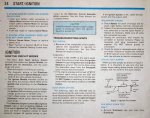
PG24.jpg

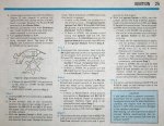
PG25.jpg

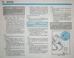
PG26.jpg

 
OP
OP
Ymehawa11

Ymehawa11

New member
Joined
Nov 20, 2016
Messages
13
Reaction score
0
thanks will dig in, the distributor is a year old but the part the TFI attaches to is not, will do more testing this weekend, thanks for the insight, lets see if I can do this without blowing something up. :) /emoticons/[email protected] 2x" width="20" height="20" />

 
OP
OP
Ymehawa11

Ymehawa11

New member
Joined
Nov 20, 2016
Messages
13
Reaction score
0
Oh yea I have learned the hard way, stay away from the Zone and Orielly I have gotten bad parts from both multi able times


miesk5

96 Bronco 5.0
Staff member
Moderator
Joined
Oct 18, 2005
Messages
9,071
Reaction score
1,019
Location
Floating in the Pacific
Yo,

Be prepared to do the Self-Test test again.

Run the engine in driveway, etc. Until it gets so up to normal operating temperature.

Hopefully it will shut down. Then do the self test.

Typical codes will be;

DTC 14 DTC 14 indicates the PIP signal output was missing pulses while the engine was running.

Check EEC system harness for:

Loose wires/connectors.

On board transmitter (two-way radio).

On board telephone, etc.

DTC 18 IDM circuit failure or SPOUT circuit grounded.

 
OP
OP
Ymehawa11

Ymehawa11

New member
Joined
Nov 20, 2016
Messages
13
Reaction score
0
it only shuts off during shift unless I push real heavy on the gas pedal

 
OP
OP
Ymehawa11

Ymehawa11

New member
Joined
Nov 20, 2016
Messages
13
Reaction score
0
power stays on, it acts like its not getting gas, but it is

 
OP
OP
Ymehawa11

Ymehawa11

New member
Joined
Nov 20, 2016
Messages
13
Reaction score
0
? I have Exhaust where the muffler connects to the Manifold. how connected could this be to the symptons?

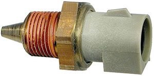
CO2 sensor looks like the first picture put only the the light tan color at the bottom

http://cds.activant.com/C2C/C01/68/541/824663110.pdf

There is no catalytic converter, it was removed some time ago and ran fine without it until now?

 
Last edited by a moderator:

miesk5

96 Bronco 5.0
Staff member
Moderator
Joined
Oct 18, 2005
Messages
9,071
Reaction score
1,019
Location
Floating in the Pacific
Yo, part 2 today,

DTC 18; we can assume SPOUT is secure and good electrically; one test is to pull it & check it for 0 ohms; if NG, replace w/suitably sized copper wire

DTC 18 IDM circuit failure or SPOUT circuit grounded

Source: by Ford via Ben Watson in How to Tune and Modify Ford Fuel Injection via books.google.com

http://books.google....8 ford&f=false

Ben doesn't mention that the wires leading to and from the SPOUTconnector can ground or or are cut by the foil shield

Foil shield covers the wires to and from the Ignition Control Module (ICM) as well as the SPOUT circuit.

DTC 14 & 18; Profile Ignition Pickup (PIP) & Troubleshooting; "...The top three leads (for PIP signal) can lose continuity with the back plate (ground) on the module when the unit is hot. You should consider a remote mounted TFI. If your TFI is failing from heat, it can give off computer codes 14 (PIP) and 18 (SPOUT). stalling/dieing or sputtering when hot but runs when it cools off. This can be caused by a faulty TFI and the biggest culprits are heat. Another culprit can be a wire grounding out. Problematic TFI's can give off codes 14 (PIP) and 18 (SPOUT)..."

Read more @ DTC 14 & 18; Profile Ignition Pickup (PIP) & Troubleshooting; "...The top three leads (for PIP signal) can lose continuity with the back plate (ground) on the module when the unit is hot. You should consider a remote mounted TFI. If your TFI is failing from heat, it can give off computer codes 14 (PIP) and 18 (SPOUT). stalling/dieing or sputtering when hot but runs when it cools off. This can be caused by a faulty TFI and the biggest culprits are heat. Another culprit can be a wire grounding out. Problematic TFI's can give off codes 14 (PIP) and 18 (SPOUT)..."

Read more @ http://broncozone.com/topic/24040-broncoshutsoff-dangerous/

 
OP
OP
Ymehawa11

Ymehawa11

New member
Joined
Nov 20, 2016
Messages
13
Reaction score
0
ok I finialy have time to dig into my Bronco again. So this is what I have noticed after driving for a week.

Thermostat get half way the it shuts down, after thermostat gets back down to the N it will start up again and run like no problem.

1. Happens only when highway acceleration with heavy traffic ( its a heavy truck so have to push her to get up to speed and stay) 

2. Temp Gage never goes farther then Half way, but when it does system spudders, back fires then wont start

My thought ECT?


miesk5

96 Bronco 5.0
Staff member
Moderator
Joined
Oct 18, 2005
Messages
9,071
Reaction score
1,019
Location
Floating in the Pacific
Yo,

Is it overheating?

Without a code;

Engine Coolant Temperature Sensor (ECT)
ect.jpg

Before you start blaming the engine coolant temperature sensor and replacing it make sure the rest of the coolant system is in good condition. All of the following items will affect the ECT:

*Coolant level
*Radiator Fan
*Water Pump 
*Water Pump and Fan Belts 
*Thermostat 
*Base Timing 
*Engines general condition 
*Harness and wire general condition

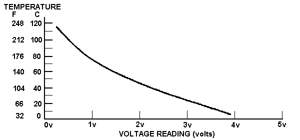
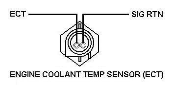
The Engine Coolant Temperature (ECT) sensor is a thermal transistor, which means it allows less electricity to pass through the sensor the warmer it gets. The ECT receives the Signal Return voltage from the EEC, then allows a certain amount to return back to the EEC. Because the ECT is in direct contact with the engine coolant flow it changes resistance in response to the temperature of that coolant.

temperature.gif

The ECT is third in command in the hierarchy of EFI sensors, this means this sensor is very important when calculating fuel ratios and timing curves. This is because of simply chemistry; fuel and spark are constants in the equation. Air is the biggest variable in combustion; it changes density greatly over a range of temperature. So keeping track of the changing temperatures of the incoming air and the engine in which it is burnt becomes very important. But due to its simplicity of design, the ECT is rarely at fault when problems occur.

Before testing the ECT or any other EFI component perform a self-test, trouble codes received during test can be used as a diagnostic tool along with other indicators. To test an ECT sensor you will need a volt meter. You can test the ECT by back probing the harness while reading the voltage returning to the EEC. Or you can removing the connector completely and test the resistance between the 2 pins on the ECT. The engine temperature must be greater than 50F (10C) to pass the KOEO Self-Test and greater than 180F (82C) to pass the KOER Self-Test. To accomplish this, the engine should be at normal operating temperature.

ect02.jpg

[SIZE=27.0046px]Ŕead more  @ [/SIZE]http://www.fuelinjectedford.com/page28.html
by  Ryan M.​

 
Last edited by a moderator:
OP
OP
Ymehawa11

Ymehawa11

New member
Joined
Nov 20, 2016
Messages
13
Reaction score
0
thanks, I will post what I come up with, I have ran the truck all weak and as long as I dont let it heat up, np

Has a new water pump and radiator. The motor was rebuilt 1 year ago, the wires are old so will check continuity if I can figure out how


miesk5

96 Bronco 5.0
Staff member
Moderator
Joined
Oct 18, 2005
Messages
9,071
Reaction score
1,019
Location
Floating in the Pacific

Members online

No members online now.

Latest posts

Forum statistics

Threads
22,516
Messages
135,945
Members
25,119
Latest member
Sgariffo
Top