yo T,
Try a Self Test for Diagnostic Trouble Codes (DTC)s by my pal, BroncoJoe19
http://broncozone.com/topic/14269-code-reader/page__pid__74587__mode__threaded
The engine temperature must be greater than 50° F for the Key On Engine Off (KOEO) Self-Test and greater than 180° F for the Key On Engine Running (KOER) Self-Test.
Run it around to heat the engine up and shift thru all gears incl Reverse. Then turn off all accessories/lights, etc.
Make sure A/C is off and transmission is in Park (automatic) or in Neutral for a Manual & release clutch.
Do Key On Engine Off (KOEO) portion first.
And Post em here according to:
KOEO
&
KOER
--------------
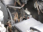
Ford re-located the ICM from Distr side to driver side hood hige area on inner fender liner in 92-96.
Pic by miesk5

Pic by
buzzbroncol Ford Part Number is on the ICM

Heat Sink is the Silver Box with cooling "fins" @ left of Center; ICM is mounted inside.
Location Diagram
http://web.archive.org/web/20110704091629/http://www.broncolinks.com/gallery_images/SpoutConnectLOC.JPG
miesk5 NOTE; use BLACK modules in 1994-1996 Broncos
Ignition Control Module (ICM) Part Numbers
Miesk5 Note; many parts store still ***** up the PN due to issues at Ford; even the Ford parts site has the wrong pns!
WELLS has it right though!
Source: by Seattle FSB (SeattleFSB)
Motorcraft - DY1077 (supercedes DY679, DY667, DY645)
Ford - 5U2Z-12A297-D (supercedes F1PZ-12A297-A)
Wells - F139
Niehoff - FF413
BWD - CBE40
Standard - LX-241
NapaEchlin - TP29
Delphi - DS10056
Transpo - FM544
With the incorrect TFI module installed, the vehicle will run, but driveability and MIL (malfunction indicator lamp) problems will result. For instance, if a gray Push Start TFI module is installed in a CCD system, the computer will not be able to control ignition dwell, and the MIL will illuminate with memory codes for the IDM circuit set, as the gray TFL module is incapable of generating an IDM signal to the computer. If a black CCD TFI module is installed in a Push Start system, dwell will remain fixed, since the SPOUT signal duty cycle never changes.
Source: by David S in Motor Service, June, 2001 via web.archive.org
Wiring Diagram in a 94 by Steve

Also see the Test for the CCD system at bottom of page
http://www.supermotors.net/registry/media/833750_1
Many also replace the
Hall Effect (Profile Ignition Pick-up (PIP) Signal, Stator, RPM) inside distr or buy a new distr.
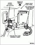
Ignition Control Module
Removal
- Remove two screws retaining ignition control module (ICM) (12A297) heat sink assembly to left fender apron.
- Disconnect harness connector from ignition control module.
- Remove two screws retaining ignition control module to heat sink and remove ignition control module.
 Installation
- Coat ignition control module baseplate with silicone compound, approximately 0.0179mm (1/32-inch) thick. Use Silicone Dielectric Compound (WA-10) D7AZ-19A331-A or equivalent meeting Ford specification ESE-M1C171-A.
- Position ignition control module onto heat sink and tighten two retaining screws to 1.2-1.8 Nm (11-16 lb-in).
- Install ignition control module heat sink assembly on left fender apron using two retaining screws, and tighten to 9-14 Nm (80-124 lb-in).
- Connect wiring to ignition control module.
TFI Module, Profile Ignition Pickup (PIP) System Diagnostic Tree & Resistance Values; Testing, Overview & Diagrams, Fender Mounted Ignition Control Module (ICM)
Source: by easyautodiagnostics.com http://easyautodiagnostics.com/ford_ign_fender/fender_mounted_module_1.php


